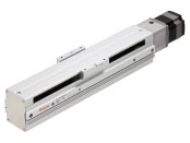
Electric Linear Slides EAS Series
EAS6X-E020-AZAAD-2

Actuator/Control Circuit
| Classificazione prodotto | Nome del prodotto | Prezzo di listino | Data di spedizione |
|---|---|---|---|
| Actuator / Control Circuit | EAS6X-E020-AZAAD-2 | - | Prodotto fuori produzione (31.3.2023 fuori produzione) |
Incluso
- Actuator, Circuit, Cable for motor (2 m), Encoder Connection Cable (2 m), Main Power Supply/Regeneration Resistor Connector (CN4), I/O Signal Connector (CN5), Connector for 24 VDC Power Supply input · Electromagnetic Brake Connector · Regeneration Unit Thermal Input · power removal signal input (CN1), Connector Wiring Lever
Specifiche
Caratteristiche
Dimensioni
Altre Specifiche
General Specifications (Motor)
| Item | AC Input | DC Input | |
|---|---|---|---|
| Thermal Class | 130 (B) [UL/CSA is certified at 105 (A).] |
||
| Insulation Resistance |
100 MΩ or more when a 500 VDC megger is applied between the following places:
|
||
| Dielectric Strength |
Sufficient to withstand the following for 1 minute. EASM4, EACM4, EASM6, EACM6
|
Sufficient to withstand the following for 1 minute. EASM2, EACM2
|
|
| Operating Environment (When operating) |
Ambient Temperature | 0~+40 °C (Non-freezing)*3 | |
| Ambient Humidity | 85 % max. (Non-condensing) | ||
| Atmosphere | No corrosive gases or dust. No exposure to water, oil or other liquids. | ||
| Degree of Protection*2 |
EASM2, EACM2: IP40 (Except for mounting surface and connector parts) EASM4, EACM4, EASM6, EACM6: IP66 (Except for mounting surface and connector parts) |
||
| Multi-Rotation Detection Range in Power OFF State |
EASM2, EACM2: ±450 revolutions (900 revolutions) EASM4, EACM4, EASM6, EACM6: ±900 revolutions (1800 revolutions) |
||
- *1
- (Only for types with electromagnetic brake)
- *2
- Motor only. The degree of protection of electric linear slide and electric cylinder is IP00.
- *3
- According to Oriental Motor’s measurement conditions.
Note
- Disconnect the motor and driver when measuring insulation resistance, or performing a dielectric strength test.
Also, do not perform these tests on the ABZO sensor part of the motor.
Driver Circuit Specifications
| Classification | Name | Built-In Controller Type |
Pulse input Type |
|
|---|---|---|---|---|
| I/O Function |
Pulse Input | − | Maximum Input Pulse Frequency: Line driver output from host controller: 1 MHz (at 50 % duty) Open-Collector Output by Host Controller: 250 kHz (at 50 % duty) Negative Logic Pulse Input (Initial value) |
|
| Direct Input | Input Points: 10 points | Input Points: 6 points | ||
| Direct Output | Output Points: 6 points | |||
| RS-485 Communication | Network Input | 16 points | − | |
| Network Output | 16 points | − | ||
RS-485 Communication Specifications
| Protocol | Modbus RTU Mode |
|---|---|
| Electrical Characteristics | EIA-485 Compliant, Straight Cable Use twisted-pair cables (TIA/EIA-568B CAT5e or better recommended). The max. total extension length is 50 m.* |
| Mode | Half duplex communication and asynchronous mode (data: 8 bits, stop bit: 1 bit or 2 bits, parity: none, even, or odd) |
| Transmission Rate | 9600 bps, 19200 bps, 38400 bps, 57600 bps, 115200 bps, and 230400 bps are available. |
| Connection Type | Up to 31 units can be connected to a single programmable controller (master device). |
- *If a specific wiring and layout causes the motor cable or power supply cable to generate a noise problem, shield the cable or use ferrite cores.
Travel Direction
| Built-in Controller Type | Pulse input type | ||
|---|---|---|---|
| Insulation Resistance |
100 MΩ or more when a 500 VDC megger is applied between the following places.
|
||
| Dielectric Strength |
Sufficient to withstand the following for 1 minute:
|
||
| Operating Environment (When operating) |
Ambient Temperature | 0~+55 °C (Non-freezing)* | |
| Ambient Humidity | 85 % max. (Non-condensing) | ||
| Atmosphere | No corrosive gases or dust. No exposure to water, oil or other liquids. | ||
| Degree of Protection | IP10 | IP20 | |
| Multi-Rotation Detection Range in Power OFF State | ± 900 revolutions (1800 revolutions) | ||
- *When installing a heat sink equivalent to an aluminum plate min. 200×200 mm, thickness 2 mm
Note
- Disconnect the motor and driver when measuring insulation resistance or conducting a dielectric strength test.
Calculating Load Moment
When a load is transported with an electric linear slide or electric cylinder (a unit equipped with shaft guide covers only), the load moment acts on the linear guide/shaft guide if the position of the load's center of gravity is offset from the center of the table/center of the shaft guide. The direction of action applies to the directions for pitching (MP), yawing (MY), and rolling (MR), depending on the position of the offset.
Even though the selected electric actuators satisfy the load mass and positioning time requirements, when the center of gravity of the load is overhung from the table's center/shaft guide’s center, the run life may decrease as a result of the load moment. Load moment calculations must be completed and whether the conditions are within specifications values must be checked. The moment applied under static conditions is the static permissible moment. The moment applied under movement is the dynamic permissible moment, and both must be checked.
Calculate the load moment of the electric linear slides and electric cylinders (units equipped with shaft guide covers only) based on loads that are applied. Check that the static permissible moment and dynamic permissible moment are within limits and check that strength is sufficient.
- *For more information on calculating static permissible moment and dynamic permissible moments, click here.
Load Moment Formula
When there are several overhung loads, etc., it is determined by the sum of moments from all loads.
For Multiple Loads (n)
Standard
Regulations and Standards Materials
Documents about compliance with regulations and standards can be downloaded from the "Data Download" tab on the product details page.
(The types of files available for download vary by product.)
Explanations of the Global Laws, Regulations and Standards can be found here.
Information about our compliance with regulations and standards for each of our product series can be found here.
Hazardous Substances
The product does not contain any substances (10 substances) exceeding the regulation values of the RoHS Directive (2011/65/EU, 2015/863/EU).
For more information about compliance with regulations on chemical substances in Oriental Motor's Products, click here.
Configurazione del sistema

Prodotti correlati
| Products | Features | ||
|---|---|---|---|
NETC02-CC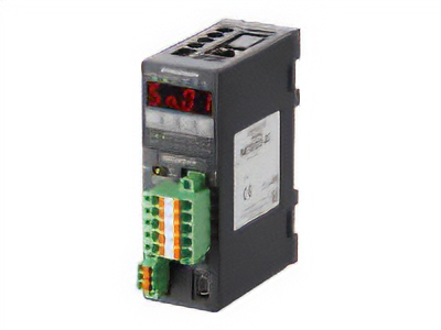
|
Features |
[CC-Link Ver. 2 Compatible] By supporting CC-Link Ver.2, you can simplify the ladder program and shorten the communication time for data sending and receiving. |
|
| Products |
NETC01-ECT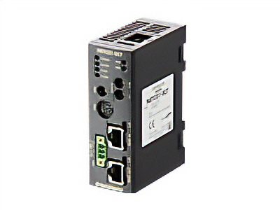
|
Features |
[EtherCAT Compatible] |
Cavi e accessori