Compact Linear Actuators DRS Series
DRS28SB1G-03NKA
Actuator/Control Circuit
Questo prodotto non è più disponibile per la vendita.
| Classificazione prodotto | Nome del prodotto | Prezzo di listino | Data di spedizione |
|---|---|---|---|
| Actuator / Control Circuit | DRS28SB1G-03NKA | - | Prodotto fuori produzione (31.3.2020 fuori produzione) |
Incluso
- Actuator, Control Circuit, I/O signal Connector, Power Connector, Operating Manual
Specifiche
Altre Specifiche
Reference Diagrams for Load Moment
Load Moment
Electromagnetic Brake Specifications
| Electromagnetic Brake Type | Power off activated type |
|---|---|
| Power Supply Input Voltage/Current |
DRS42: 24 VDC±5 % 0.08 A DRS60: 24 VDC±5 % 0.25 A |
| Brake Activation/Release Time | Activation time: 20 ms Release time: 30 ms |
| Time Rating | Continuous |
Driver Circuit Specifications
| Product Name | DRSD07A-KA | DRSD18A-KA | DRSD33A-KA | |
|---|---|---|---|---|
| Power Supply Input | Voltage | 24 VDC±10 % | ||
| Current | 0.8 A | 1.6 A | 3.5 A | |
| Speed and Position Control Command | Pulse Input | |||
| Maximum Input Pulse Frequency | 250 kHz (at 50 % duty cycle) | |||
| Protective Function | When the following protective functions are activated, an alarm signal will output, and the motor will come to a coasting stop. Overload protection, overvoltage protection, abnormal speed error protection, overspeed, EEPROM data error, sensor error, system error | |||
| Input Signals | Photocoupler input, input resistance: 220 Ω, input current 7~20 mA [CW (forward) pulse, CCW (backward) pulse (negative logic pulse input), pulse/travel direction switching (negative logic pulse input), all windings off, alarm clear, resolution select] |
|||
| Output Signals | Photocoupler and open-collector output, external use conditions 30 VDC max., 15 mA max. (positioning completion, alarm, timing) Transistor and open-collector output, external use conditions 30 VDC, 15 mA max. (feedback pulses phases A and B) |
|||
General Specifications
Values are after rated operation at normal ambient temperature and humidity.
| Item | Actuator Part (Motor) | Driver | |
|---|---|---|---|
| Motor Thermal Class | 130 (B) [UL/CSA Standard obtainment is certified with 105(A)]. | − | |
| Insulation Resistance |
100 MΩ or more when a 500 VDC megger is applied between the following places:
|
100 MΩ or more when a 500 VDC megger is applied between the following places:
|
|
| Dielectric Strength |
Sufficient to withstand the following for 1 minute:
|
Sufficient to withstand the following for 1 minute:
|
|
| Operating Environment (When Operating) |
Ambient Temperature | 0~+40 °C (Non-freezing) | |
| Ambient Humidity | 85 % max. (Non-condensing) | ||
| Atmosphere | No corrosive gases or dust. No exposure to water, oil or other liquids. | ||
Note
- Do not measure insulation resistance or perform a dielectric strength test the actuator and driver are connected.
Configurazione del sistema
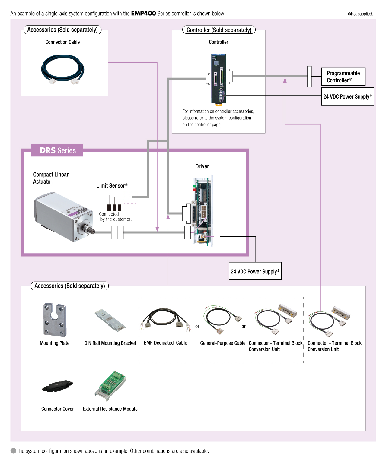
Cavi e accessori
close