Brushless Motors BX Series
BX460CM-50FR
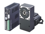
Gearhead / Motor / Control Circuit


| Classificazione prodotto | Nome del prodotto | Prezzo di listino | Data di spedizione |
|---|---|---|---|
| Gearhead / Motor / Control Circuit | BX460CM-50FR | - | Prodotto fuori produzione (31.3.2019 fuori produzione) |
Incluso
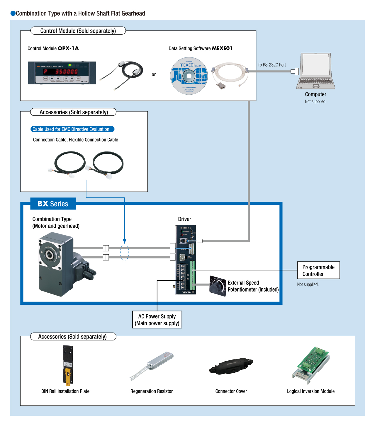
- Motor, Gearhead, Control Circuit, External Speed Potentiometer (with Signal Line), Mounting Bracket for Control Circuit (with Screws), Mounting Screws, Parallel Key, Safety Cover (with Screws), Operating Manual
Specifiche
Scarica i dati
Altre Specifiche
Common Specifications
| Item | Specifications |
|---|---|
| Input Signals* | Photocoupler input method Input resistance 2.3kΩ Internal power supply voltage +15V CW input, CCW input, speed data selection input, motor control release (FREE) input, Brake input (at alarm output: alarm reset input) |
| Output Signals* | Open-collector output 4.5~26.4 VDC Alarm output, busy output (at alarm output: alarm pulse output): 40 mA max. Speed output ASG, BSG: 20mA or less |
| Protective Function | When the following protective functions are activated, the motor will coast to a stop, (Electromagnetic brake motors will be braked) and alarm output will be turned off. The driver alarm LED will be blinking the number of times shown in parentheses (alarm pulses will be output).
|
| Maximum Extension Distance | Motor and driver distance 20.4 m (when an accessory connection cable is used) |
| Time Rating | Continuous |
-
The available input signals and output signals differ between the basic model and the system upgrade and between the speed control mode and the position control mode when the system is upgraded.
General Specifications
| Item | Motor | Driver | |
|---|---|---|---|
| Insulation Resistance | 100 MΩ or more when a 500 VDC megger is applied between the windings and the case after continuous operation under normal ambient temperature and humidity. (Except for the encoder) |
After continuous operation at normal ambient temperature and humidity, the measurement value between the power supply terminal and the case and the power supply terminal and the I/O signal terminal is 100 MΩ min. using a 500 VDC megger. |
|
| Dielectric Strength | No abnormality is observed even with an application of 1.5 kVAC at 50 Hz between the coils and the case for 1 minute after continuous operation at normal ambient temperature and humidity. (Except for the encoder) |
No abnormality is observed even with an application of 1.5 kVAC at 50 Hz between the power supply terminal and the case or 1.8 kVAC at 50 Hz between the power supply terminal and the I/O signal terminal for 1 minute after continuous operation at normal ambient temperature and humidity. |
|
| Temperature Rise | After rated continuous operation at normal ambient temperature and humidity, the measured value using the thermocouple method is 50 °Cmax. for the temperature rise of the coils and 40 °C max. *1 for the temperature rise on the case surface. |
After rated continuous operation at normal ambient temperature and humidity, the measurement value of the temperature rise of the heat sink is 50 °C max. using the thermocouple method. |
|
| Operating Environment | Ambient Temperature | 0∼+50°C (Non-freezing) | |
| Ambient Humidity | 85 % max. (Non-condensing) | ||
| Altitude | Up to 1000 m above sea level | ||
| Atmosphere | Cannot be used in special environments such as corrosive gas, no dust, radioactive materials, magnetic fields, or vacuums | ||
| Vibration | Not subject to continuous vibration or excessive shock In conformance with JIS C 60068-2-6, "Sine-wave vibration test method" Frequency Range: 10~55 Hz, Half Amplitude: 0.15 mm, Sweep Direction: 3 directions (X, Y, Z), Number of Sweeps: 20 times |
||
| Storage Conditions*2 | Ambient Temperature | -20∼+60°C (Non-freezing) | -25~+70°C (Non-freezing) |
| Ambient Humidity | 85 % max. (Non-condensing) | ||
| Altitude | Up to 3000 m above sea level | ||
| Thermal Class | UL/CSA Standards: 105 (A), EN Standards: 120 (E) | − | |
| Degree of Protection | IP54 (Excluding the installation surface of the round shaft type and connectors) | IP10 | |
- *1
- Attach round shaft types to a heat sink (Material: aluminum) of one of the following sizes to maintain a motor case surface temperature of 90 °C max.
30 W Type: 115×115 mm, 5 mm thickness, 60 W Type: 135×135 mm, 5 mm thickness, 120 W Type: 165×165 mm, 5 mm thickness,
200 W Type: 200×200 mm, 5 mm thickness, 400 W Type: 250×250 mm, 6 mm thickness - *2
- The value for storage condition applies to short periods such as the period during transport.
Note
- Do not measure insulation resistance or perform a dielectric strength test the motor and driver are connected.
Speed Control Specifications
- Standard Model: These specifications apply when using the basic motor and driver package.
- When the System is Upgraded: These specifications apply when using the control module sold separately (OPX-1A or MEXE01).
| Item | Standard Model | When the System is Upgraded |
|---|---|---|
| Speed Control Range | 30~3000 r/min (at analog Setting) | 30~3000 r/min (at analog Setting) 3~3000 r/min (setting in 1 r/min units at digital setting) |
| Speed Setting Methods | Select one of the following methods.
|
Select one of the following methods.
|
| Acceleration Time and Deceleration Time | 0.1∼15 sec. (3000 r/min at no load) Acceleration Time and Deceleration Time are common to all Speed Data |
Select one of the following methods. (3000 r/min at no load)
|
| Multi-Speed Setting Methods |
2-Speed:
*1-Speed by Internal Speed Potentiometer and 1-Speed by External Speed Potentiometer (20kΩ, 1/4W) or External DC Voltage (0~5VDC)
|
Select one of the following methods.
|
Permissible Radial Load and Permissible Axial Load
Combination type with a parallel shaft gearhead
| Product Name | Gear Ratio | Permissible Radial Load | Permissible Axial Load N |
|
|---|---|---|---|---|
| 10 mm From Shaft End N |
20 mm From Shaft End N |
|||
| BX230■-□S | 5 | 100 | 150 | 40 |
| 10, 15, 20 | 150 | 200 | ||
| 30, 50, 100, 200 | 200 | 300 | ||
| BX460■-□S | 5 | 200 | 250 | 100 |
| 10, 15, 20 | 300 | 350 | ||
| 30, 50, 100, 200 | 450 | 550 | ||
| BX5120■-□S | 5 | 300 | 400 | 150 |
| 10, 15, 20 | 400 | 500 | ||
| 30, 50, 100, 200 | 500 | 650 | ||
| BX6200■-□S BX6400S-□S BX6400SM-□S |
5, 10, 15, 20 | 550 | 800 | 200 |
| 30, 50 | 1000 | 1250 | 300 | |
| 100, 200 | 1400 | 1700 | 400 | |
Combination type with a hollow shaft flat gearhead
| Product Name | Gear Ratio | Permissible Radial Load | Permissible Axial Load N |
|
|---|---|---|---|---|
| 10 mm From the Gearhead Mounting Surface N |
20 mm From the Gearhead Mounting Surface N |
|||
| BX230■-□FR | 5, 10 | 450 | 370 | 200 |
| 15, 20, 30, 50, 100, 200 | 500 | 400 | ||
| BX460■-□FR | 5, 10 | 800 | 660 | 400 |
| 15, 20, 30, 50, 100, 200 | 1200 | 1000 | ||
| BX5120■-□FR | 5, 10 | 900 | 770 | 500 |
| 15, 20 | 1300 | 1110 | ||
| 30, 50, 100, 200 | 1500 | 1280 | ||
| BX6200■-□FR BX6400S-□FR BX6400SM-□FR |
5*, 10 | 1230 | 1070 | 800 |
| 15, 20 | 1680 | 1470 | ||
| 30, 50, 100 | 2040 | 1780 | ||
- *BX6400S-□FR, BX6400SM-□FR only.
Round Shaft Type
| Product Name | Permissible Radial Load | Permissible Axial Load | |
|---|---|---|---|
| 10 mm From Shaft End N |
20 mm From Shaft End N |
||
| BX230■-A | 87.2 | 107 | Half of the motor mass or less |
| BX460■-A | 117 | 137 | |
| BX230■-A | 156 | 176 | |
| BX6200■-A BX6400S-A BX6400SM-A |
197 | 221 | |
Permissible Radial Load Calculation
The formula for calculating the permissible radial load varies depending on the mechanism.
When One Side of the Load Shaft is Not Supported by the Bearing Unit
The radial load is the most difficult mechanism. A Stepped Type Load Shaft is recommended.
| Product Name | Permissible Radial load W [N] |
|---|---|
| GFS2G□FR |
\(\begin{align} \mathrm{W} [\mathrm{N}] = \frac{36}{36 + \mathrm{Lp}} \times \mathrm{F}_0 [\mathrm{N}] \end{align}\)
|
| GFS4G□FR |
\(\begin{align} \mathrm{W} [\mathrm{N}] = \frac{40}{40 + \mathrm{Lp}} \times \mathrm{F}_0 [\mathrm{N}] \end{align}\)
|
| GFS5G□FR |
\(\begin{align} \mathrm{W} [\mathrm{N}] = \frac{50}{50 + \mathrm{Lp}} \times \mathrm{F}_0 [\mathrm{N}] \end{align}\)
|
| GFS6G□FR |
\(\begin{align} \mathrm{W} [\mathrm{N}] = \frac{60}{60 + \mathrm{Lp}} \times \mathrm{F}_0 [\mathrm{N}] \end{align}\)
|
When One Side of the Load Shaft is Supported by the Bearing Unit
| Product Name | Permissible Radial load W [N] |
|---|---|
| GFS2G□FR GFS4G□FR GFS5G□FR GFS6G□FR |
\(\begin{align} \mathrm{W} [\mathrm{N}] = \frac{\mathrm{B}}{\mathrm{B} - \mathrm{Lp}} \times \mathrm{F}_0 [\mathrm{N}] \end{align}\)
|
| Product Name | Rotation Speed | Gear Ratio | F0 [N] |
|---|---|---|---|
| GFS2G□FR | At 3~3000 r/min | 5, 10 | 570 |
| 15~200 | 630 | ||
| At 4000 r/min | 5, 10 | 520 | |
| 15~200 | 580 | ||
| GFS4G□FR | At 3~3000 r/min | 5, 10 | 1000 |
| 15~200 | 1500 | ||
| At 4000 r/min | 5, 10 | 910 | |
| 15~200 | 1370 | ||
| GFS5G□FR | At 3~3000 r/min | 5, 10 | 1080 |
| 15, 20 | 1550 | ||
| 30~200 | 1800 | ||
| At 4000 r/min | 5, 10 | 980 | |
| 15, 20 | 1430 | ||
| 30~200 | 1680 | ||
| GFS6G□FR | At 3~3000 r/min | 5, 10 | 1430 |
| 15, 20 | 1960 | ||
| 30~100 | 2380 | ||
| At 4000 r/min | 5, 10 | 1320 | |
| 15, 20 | 1810 | ||
| 30~100 | 2210 |
Vertical Operation (Gravitational operation)
The BX Series achieves stable speed control even during gravitational operation.
During vertical operation (gravitational operation), shown in the figure below, normally an external force causes the motor to rotate and function as a power generator. If this energy is applied to the driver, an error will occur.
The accessory regeneration resistor (sold separately) can convert regenerative energy into thermal energy for dissipation. Use the accessory regeneration resistor when using the motor for vertical operation or when braking a large inertial load quickly.
| Regeneration Resistor Product Name | Applicable Product | Continuous Regenerative Power | Instantaneous Regenerative Power |
|---|---|---|---|
| EPRC-400P | BX230 (Rated Output Power 30 W) | 100 W | 240 W |
| BX460 (Rated Output Power 60 W) | |||
| BX5120 (Rated Output Power 120 W) | |||
| RGB100 | BX6200 (Rated Output Power 200 W) | 100 W | 800 W |
| BX6400 (Rated Output Power 400 W) |
- Install in a place that has the same heat radiation capability as the heat sink (Material: Aluminum 350 × 350 mm, 3 mm thickness).
About Regenerative Power
The regenerative power can be estimated using the formula below. Use the calculated value as a reference.
Regenerative Power (W) = 0.1047 × TL [N·m] × N [r/min]
TL: Load Torque N: Rotation Speed
- Use electromagnetic brake type for gravitational operation.
Gravitational Operation Capability
- Continuous gravitational operation exceeding the range of continuous regeneration resistor will trigger the built-in thermal protector (150°C).
Configurazione del sistema