Brushless Motors BLU Series
BLU590A-20FR
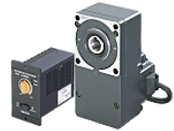
Gearhead / Motor / Control Circuit
Questo prodotto non è più disponibile per la vendita.
| Classificazione prodotto | Nome del prodotto | Prezzo di listino | Data di spedizione |
|---|---|---|---|
| Gearhead / Motor / Control Circuit | BLU590A-20FR | - | Prodotto fuori produzione (31.3.2019 fuori produzione) |
Incluso
- Motor, Control Circuit, Gearhead, Power Supply Cable, Mounting Screw for Circuit, Short Bar, Mounting Screws, Parallel Key, Safety Cover (with Screws), Operating Manual
Specifiche
Scarica i dati
Altre Specifiche
Common Specifications
| Item | Specifications |
|---|---|
| Speed Setting Methods | Speed potentiometer on front panel |
| Acceleration Time and Deceleration Time | 0.5~10 sec: 2000 r/min at no load (However, this may vary depending on the size of the load.) Common settings are made using the acceleration time and deceleration time potentiometers on the back of the front panel. |
| Input Signals | Photocoupler Input Method (reinforced insulation photocoupler) Input Resistance 2.4kΩ Internal Power Supply Voltage 14 VDC±10% Operated by internal power supply Common to CW Input and CCW Input Sync Logic/Source Logic Selection... Switchable by Selection Switch: Factory settings Sink logic |
| Output Signals | Open-collector output (reinforced insulation photocoupler) Operated by external power supply Operating conditions 4.5~26.4 VDC 0.5~10 mA Common to Alarm Output and Speed Output |
| Protective Functions* | When the following protective functions are activated, the motor will coast to a stop, and the ALARM output will be turned off. When the overload protective function is activated, the alarm LED of the driver will be blinking. It will light up when other protective functions are activated.
|
| Maximum Extension Distance | Between motor and driver 10.5m (when an accessory connection cable is used) |
| Time Rating | Continuous |
- *The BLU series cannot control the speed control of the motor in applications where the motor side is turned from the load side, such as gravitational operation.
When a load exceeding the permissible load inertia value is driven, or when gravitational operation is performed, the overvoltage protective function works to bring the motor to a coasting stop.
General Specifications
| Item | Motor | Driver | |
|---|---|---|---|
| Insulation Resistance | 100 MΩ or more when a 500 VDC megger is applied between the windings and the case after continuous operation under normal ambient temperature and humidity. |
After continuous operation at normal ambient temperature and humidity, the value measured with a 500 VDC megger between the power supply terminal and the protective earth terminal, and between the power supply terminal and the I/O signal terminal is 100 MΩ min. |
|
| Dielectric Strength | No abnormality is observed even with an application of 1.5 kVAC at 50 Hz between the coils and the case for 1 minute after continuous operation at normal ambient temperature and humidity. |
No abnormality is observed even with an application of 1.8 kVAC at 50 Hz between the power supply terminal and the protective earth terminal or 3 kVAC at 50 Hz between the power supply terminal and the signal I/O terminal for 1 minute after continuous operation at normal ambient temperature and humidity. |
|
| Temperature Rise | After continuous operation at normal ambient temperature and humidity, the temperature rise of the coil measured by the thermocouple method is 60 °C max. and that of the case surface is 50 °C max*1. |
− | |
| Operating Environment | Ambient Temperature | UL, CSA Standards 0~+40°C (Non-freezing) EN Standards 0~+50°C (Non-freezing) |
0~+40°C (Non-freezing) |
| Ambient Humidity | 85 % max. (Non-condensing) | ||
| Altitude | Up to 1000 m above sea level | ||
| Atmosphere | Cannot be used in special environments such as corrosive gas, no dust, radioactive materials, magnetic fields, or vacuums | ||
| Vibration | Not subject to continuous vibration or excessive shock In conformance with JIS C 60068-2-6, "Sine-wave vibration test method" Frequency Range: 10~55 Hz, Half Amplitude: 0.15 mm, Sweep Direction: 3 directions (X, Y, Z), Number of Sweeps: 20 times |
||
| Storage Conditions*2 | Ambient Temperature | -25~+70°C (Non-freezing) | |
| Ambient Humidity | 85 % max. (Non-condensing) | ||
| Altitude | Up to 3000 m above sea level | ||
| Thermal Class | UL/CSA Standards: 105 (A), EN Standards: 120 (E) | − | |
| Degree of Protection | IP65 (Excluding the installation surface of the round shaft type and connectors) | IP10 | |
- *1
- Attach round shaft types to a heat sink (Material: aluminum) of one of the following sizes to maintain a motor case surface temperature of 90 °C max.
25 W Type: 135x135 mm, 5 mm thickness
40 W Type: 165x165 mm, 5 mm thickness
90 W Type: 200x200 mm, 5 mm thickness - *2
- The value for storage condition applies to short periods such as the period during transport.
Note
- Do not measure insulation resistance or perform a dielectric strength while the motor and driver are connected.
Permissible Radial Load and Permissible Axial Load
Combination type with a parallel shaft gearhead
| Product Name | Gear Ratio | Permissible Radial Load | Permissible Axial Load N |
|
|---|---|---|---|---|
| 10 mm From Shaft End N |
20 mm From Shaft End N |
|||
| BLU220■-□ | 5 | 100 | 150 | 40 |
| 10, 15, 20 | 150 | 200 | ||
| 30, 50, 100, 200 | 200 | 300 | ||
| BLU440■-□ | 5 | 200 | 250 | 100 |
| 10, 15, 20 | 300 | 350 | ||
| 30, 50, 100, 200 | 450 | 550 | ||
| BLU590■-□ | 5 | 300 | 400 | 150 |
| 10, 15, 20 | 400 | 500 | ||
| 30, 50, 100, 200 | 500 | 650 | ||
Combination type with a hollow shaft flat gearhead
| Product Name | Gear Ratio | Permissible Radial Load | Permissible Axial Load N |
|
|---|---|---|---|---|
| 10 mm From the Gearhead Mounting Surface N |
20 mm From the Gearhead Mounting Surface N |
|||
| BLU220■-□FR | 5, 10 | 450 | 370 | 200 |
| 15, 20, 30, 50, 100, 200 | 500 | 400 | ||
| BLU440■-□FR | 5, 10 | 800 | 660 | 400 |
| 15, 20, 30, 50, 100, 200 | 1200 | 1000 | ||
| BLU590■-□FR | 5, 10 | 900 | 770 | 500 |
| 15, 20 | 1300 | 1110 | ||
| 30, 50, 100, 200 | 1500 | 1280 | ||
Round Shaft Type
| Product Name | Permissible Radial Load | Permissible Axial Load | |
|---|---|---|---|
| 10 mm From Shaft End N |
20 mm From Shaft End N |
||
| BLU220■-A | 70 | 100 | Half of the motor mass or less |
| BLU440■-A | 120 | 140 | |
| BLU590■-A | 160 | 170 | |
Permissible Radial Load Calculation
The formula for calculating the permissible radial load varies depending on the mechanism.
When One Side of the Load Shaft is Not Supported by the Bearing Unit
The radial load is the most difficult mechanism. A Stepped Type Load Shaft is recommended.
F0 [N]:
Permissible Radial Load at the Flange-Mounting Surface Position
Lp [mm]:
Distance from Flange-Mounting Surface to Radial Load Point
B [mm]:
Distance from Flange-Mounting Surface to Bearing Unit
| Product Name | Permissible Radial load W [N] |
|---|---|
| GFS2G□FR |
\(\begin{align} \mathrm{W} [\mathrm{N}] = \frac{36}{36 + \mathrm{Lp}} \times \mathrm{F}_0 [\mathrm{N}] \end{align}\)
|
| GFS4G□FR |
\(\begin{align} \mathrm{W} [\mathrm{N}] = \frac{40}{40 + \mathrm{Lp}} \times \mathrm{F}_0 [\mathrm{N}] \end{align}\)
|
| GFS5G□FR |
\(\begin{align} \mathrm{W} [\mathrm{N}] = \frac{50}{50 + \mathrm{Lp}} \times \mathrm{F}_0 [\mathrm{N}] \end{align}\)
|
| GFS6G□FR |
\(\begin{align} \mathrm{W} [\mathrm{N}] = \frac{60}{60 + \mathrm{Lp}} \times \mathrm{F}_0 [\mathrm{N}] \end{align}\)
|
When One Side of the Load Shaft is Supported by the Bearing Unit
| Product Name | Permissible Radial load W [N] |
|---|---|
| GFS2G□FR GFS4G□FR GFS5G□FR GFS6G□FR |
\(\begin{align} \mathrm{W} [\mathrm{N}] = \frac{\mathrm{B}}{\mathrm{B} - \mathrm{Lp}} \times \mathrm{F}_0 [\mathrm{N}] \end{align}\)
|
| Product Name | Rotation Speed | Gear Ratio | F0 [N] |
|---|---|---|---|
| GFS2G□FR | At 3~3000 r/min | 5, 10 | 570 |
| 15~200 | 630 | ||
| At 4000 r/min | 5, 10 | 520 | |
| 15~200 | 580 | ||
| GFS4G□FR | At 3~3000 r/min | 5, 10 | 1000 |
| 15~200 | 1500 | ||
| At 4000 r/min | 5, 10 | 910 | |
| 15~200 | 1370 | ||
| GFS5G□FR | At 3~3000 r/min | 5, 10 | 1080 |
| 15, 20 | 1550 | ||
| 30~200 | 1800 | ||
| At 4000 r/min | 5, 10 | 980 | |
| 15, 20 | 1430 | ||
| 30~200 | 1680 | ||
| GFS6G□FR | At 3~3000 r/min | 5, 10 | 1430 |
| 15, 20 | 1960 | ||
| 30~100 | 2380 | ||
| At 4000 r/min | 5, 10 | 1320 | |
| 15, 20 | 1810 | ||
| 30~100 | 2210 |
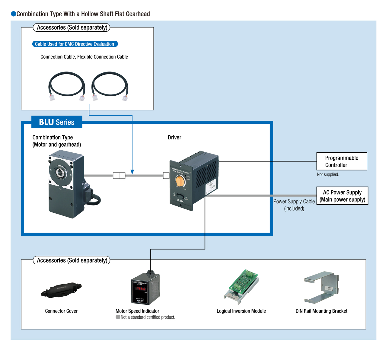
Configurazione del sistema
Cavi e accessori
close