Inverters BHF Series
BHF62CT-3
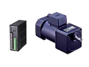
Gearhead / Motor / Control Circuit
Questo prodotto non è più disponibile per la vendita.
| Classificazione prodotto | Nome del prodotto | Prezzo di listino | Data di spedizione |
|---|---|---|---|
| Gearhead / Motor / Control Circuit | BHF62CT-3 | - | Prodotto fuori produzione (31.3.2019 fuori produzione) |
Incluso
- Motor, Control Circuit, Gearhead, Mounting Bracket for Control Circuit (with Screws), Mounting Screws, Parallel Key, Operating Manual
Specifiche
Scarica i dati
Altre Specifiche
Common Specifications
| Item | Specifications |
|---|---|
| Slow Start/ Slow Down |
Approx. 0.1~25 seconds (at 1000 r/min) |
| Speed Setting Methods | Set 1 method from the following. - Internal Speed Potentiometer (1 pc) - External Speed Potentiometer (20kΩ 1/4W) - DC Voltage Control (0~5 VDC) |
| Input Signals | Photocoupler Input Method, Input Resistance 2.3kΩ, Operates with Internal Power Supply 12VDC Common to CW/CCW, speed setting input selection, slow down, alarm reset |
| Output Signals | Open-Collector Output Operated by External Power Supply Usage Conditions 26.4 VDC 10 mA max. Speed Monitor Output (12P/R), Alarm Output |
| Protective Functions |
When the following protective functions are activated,
|
| Maximum Extension Distance | 50 m between motor and inverter |
| Time Rating | Continuous |
General Specifications
| Item | Motor | Inverter |
|---|---|---|
| Insulation Resistance | After rated operation at normal ambient temperature and humidity, the measurement between the coils and the case is 100 MΩ min. using a 500 VDC megger. | After rated operation at normal ambient temperature and humidity, the value measured with a 500 VDC megger between the power supply input terminal and the protective earth terminal, and between the power supply input terminal and the I/O signal terminal is min. 100 MΩ. |
| Dielectric Strength | No abnormality is observed even with an application of 1.5 kVAC at 50 Hz between the coils and the case for 1 minute after rated operation at normal ambient temperature and humidity. | After rated operation at normal ambient temperature and humidity, no abnormality is observed when 50 Hz or 60 Hz, 1.5 kVAC is applied between the power supply input terminal and the protective earth terminal for 1 minute, and 50 Hz or 60 Hz, 3 kVAC is applied between the power supply input terminal and the I/O terminal for 1 minute. |
| Temperature Rise | After rated operation under normal ambient temperature and humidity, the winding temperature rise measured by the resistance change method with the gearhead or equivalent heat sink * attached to the motor is 70 °C max. | − |
| Operating Temperature Range | -10~+40°C (at 100 V and 200 V: -10~+50°C) (Non-freezing) | 0∼+50°C (Non-freezing) |
| Operating Humidity Range | 85 % max. (Non-condensing) | 85 % max. (Non-condensing) |
| Thermal Class | 130(B) | - |
| Degree of Protection | IP54 (Excluding mounting surface of the Round Shaft Type.) | IP10 |
- *Heat Sink Size: 230×230 mm, 5 mm thickness (Material: Aluminum)
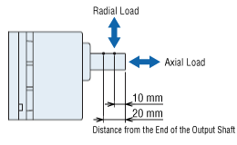
Permissible Radial Load and Permissible Axial Load
| Product Name | Gear Ratio | Permissible Radial Load | Permissible Axial Load N |
|
|---|---|---|---|---|
| 10 mm From Shaft End N |
20 mm From Shaft End N |
|||
| BHF62 ■T-□RH BHF62 ■MT-□RH |
5~30 | 1200* | 1100* | 300 |
| 50~180 | 2200* | 2000* | ||
| BHF62 ■T-□RA BHF62 ■MT-□RA |
5~30 | 900 | 1000 | 300 |
| 50~180 | 1700 | 1850 | ||
| BHF62 ■T-□ BHF62 ■MT-□ |
3~30 | 550 | 800 | 200 |
| 50~180 | 650 | 1000 | ||
- *For the hollow shaft type, the permissible radial load is the value at the distance from the mounting surface of the flange.
Configurazione del sistema
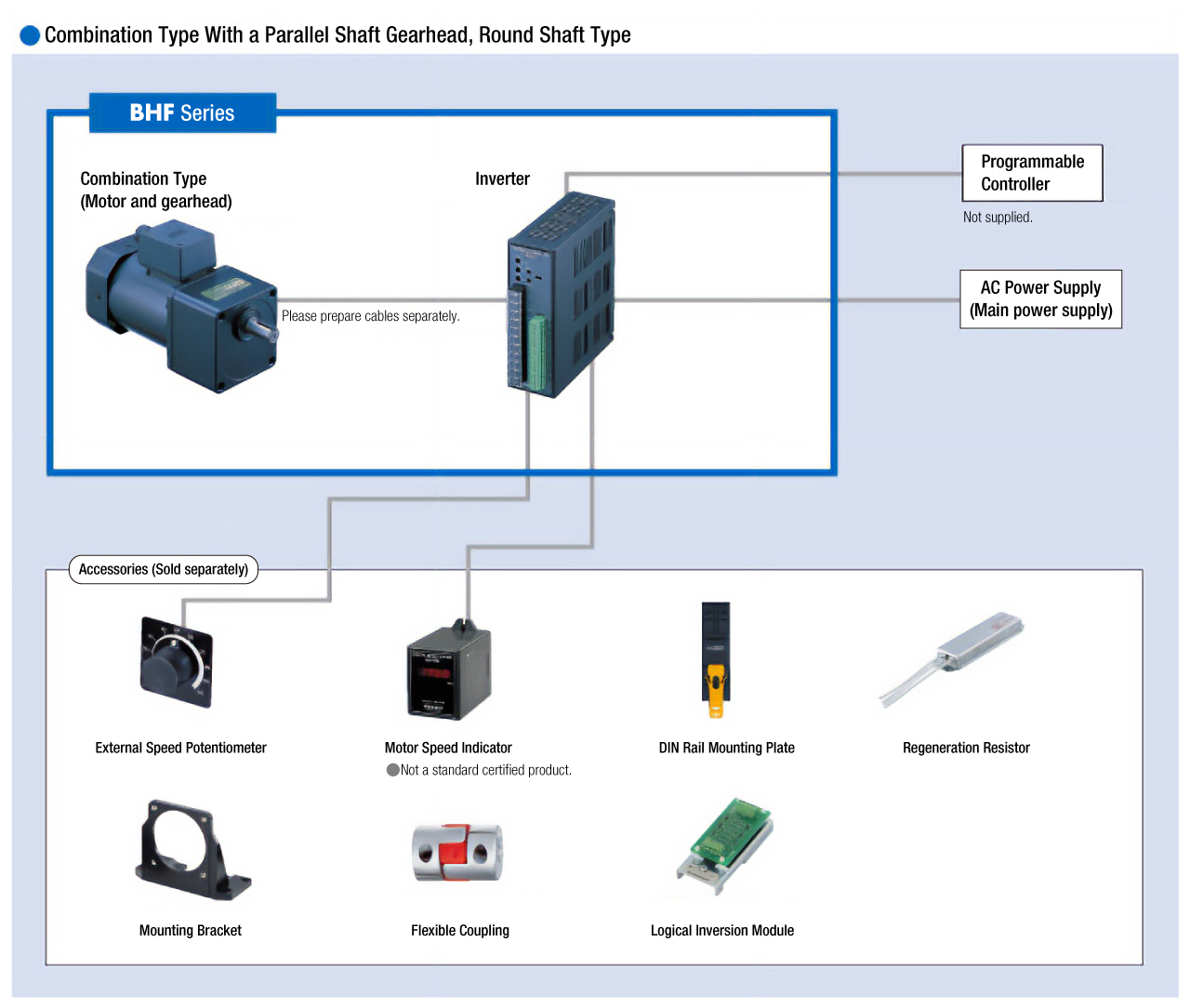
Cavi e accessori
close