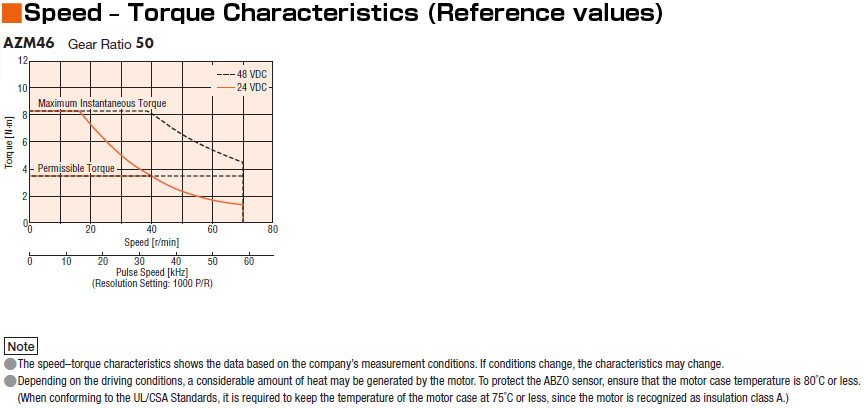
αSTEP Battery-Free Built-In Absolute Encoder AZ Series
AZM46AKH-HS50
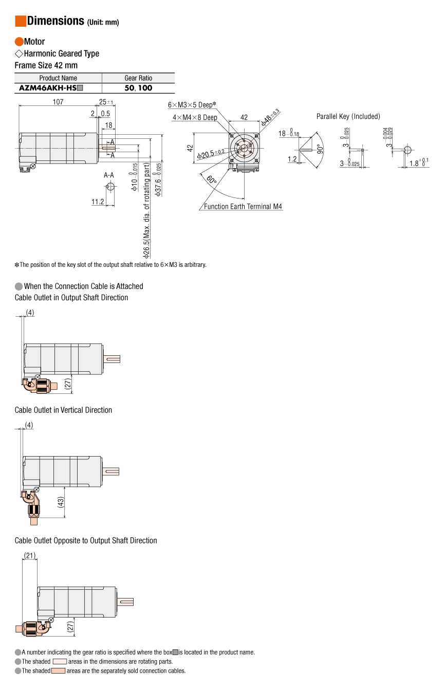
Motor


| Classificazione prodotto | Nome del prodotto | Prezzo di listino | Data di spedizione |
|---|---|---|---|
| Motor | AZM46AKH-HS50 | 855.00 € | Up to 5 pcs Estimated Ship 6weeks |
Notice: The shipping date refers to the time of dispatch from the warehouse in Düsseldorf/Germany. Shipments with 30 pieces or more will require air freight.
Incluso
- Motor: Parallel Key
Specifiche
Caratteristiche
Dimensioni
Scarica i dati
Altre Specifiche
General Specifications
| Motor | Driver | ||
|---|---|---|---|
| Thermal Class | 130(B) [UL/CSA Standards acquisition is certified at 105 (A).] |
− | |
| Insulation Resistance | 100 MΩ or more when a 500 VDC megger is applied between the following places.
|
100 MΩ or more when a 500 VDC megger is applied between the following places.
|
|
| Dielectric Strength |
Sufficient to withstand the following for 1 minute: AZM14, AZM15, AZM24, AZM26
AZM46, AZM48, AZM66, AZM69
|
− | |
| Operating Environment (when operating) |
Ambient Temperature | 0~+40 °C (Non-freezing) | 0~+50 °C (Non-freezing) |
| Ambient Humidity | 85 % max. (Non-condensing) | ||
| Atmosphere | Cable type: No corrosive gases or dust. No exposure to water, oil or other liquids. Connector type: No corrosive gases or dust. No exposure to oil or other liquids. |
No corrosive gases or dust. No exposure to water, oil or other liquids. | |
| Degree of Protection |
Cable type (except for mounting surface and connector part): Connector type (when the connection cable is connected. |
IP10 | |
| Stop Position Accuracy |
AZM14, AZM15, AZM24, AZM26: ±5 arcmin (±0.083˚) AZM46, AZM48: ±4 arcmin (±0.067˚) AZM66, AZM69: ±3 arcmin (±0.05˚) |
||
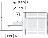
| Shaft Runout | 0.05 T.I.R. (mm)*3 | − | |
| Concentricity of Installation Pilot to the Shaft |
0.075 T.I.R. (mm)*3 | − | |
| Perpendicularity of Mounting Surface to the Shaft |
0.075 T.I.R. (mm)*3 | − | |
| Multi-Rotation Detection Range in Power OFF State |
AZM14, AZM15, AZM24, AZM26: ±450 rotations (900 rotations) AZM46, AZM48, AZM66, AZM69: ±900 rotations (1800 rotations) |
||
- *1
- (Only for types with electromagnetic brake)
- *2
- When the motor cable shape is horizontal pull-out
- *3
- T.I.R. (Total Indicator Reading): The total dial gauge reading when the measurement section is rotated once centered on the reference axis center.
Note
- Disconnect the motor and driver when measuring insulation resistance, or conducting a dielectric strength test.
Also, do not conduct these tests on the ABZO sensor part of the motor.
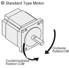
Rotation Direction
This indicates the rotation direction when viewed from the output shaft side.
The rotation direction of the gearhead output shaft relative to the standard type motor output shaft varies depending on the gear type and gear ratio. Please check the following table.
| Type | Gear Ratio | Rotation Direction Relative to Motor Output Shaft |
|---|---|---|
| TS geared | 3.6, 7.2, 10 | Same direction |
| 20, 30 | Opposite direction | |
|
PS geared PN geared HPG geared FC geared |
Overall gear ratio | Same direction |
| Harmonic geared | Overall gear ratio | Opposite direction |
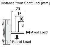
Permissible Radial Load and Permissible Axial Load
| Type | Motor Frame Size Dimension |
Motor Product Name |
Gear Ratio | Permissible Radial Load | Permissible Axial Load |
||||
|---|---|---|---|---|---|---|---|---|---|
| Distance From Shaft End [mm] | |||||||||
| 0 | 5 | 10 | 15 | 20 | |||||
| Standard Type | 20 mm | AZM14 AZM15 AZME14 |
- | 12 | 15 | - | - | - | 3 |
| 28 mm | AZM24 AZM26 AZME24 |
25 | 34 | 52 | - | - | 5 | ||
| 42 mm | AZM46 | 35 | 44 | 58 | 85 | - | 15 | ||
| AZM48 | 30 | 35 | 44 | 58 | 85 | ||||
| 60 mm | AZM66 AZM69 |
90 | 100 | 130 | 180 | 270 | 30 | ||
| 85 mm | AZM98 AZM911 |
260 | 290 | 340 | 390 | 480 | 60 | ||
| TS Geared Type | 42 mm | AZM46 | 3.6, 7.2, 10 | 20 | 30 | 40 | 50 | - | 15 |
| 20, 30 | 40 | 50 | 60 | 70 | - | ||||
| 60 mm | AZM66 | 3.6, 7.2, 10 | 120 | 135 | 150 | 165 | 180 | 40 | |
| 20, 30 | 170 | 185 | 200 | 215 | 230 | ||||
| 90 mm | AZM98 | 3.6, 7.2, 10 | 300 | 325 | 350 | 375 | 400 | 150 | |
| 20, 30 | 400 | 450 | 500 | 550 | 600 | ||||
| PS geared type | 28 mm | AZM24 | 7.2, 10 | 45 | 60 | 80 | 100 | - | 40 |
| 42 mm | AZM46 | 5 | 70 | 80 | 95 | 120 | - | 100 | |
| 7.2 | 80 | 90 | 110 | 140 | - | ||||
| 10 | 85 | 100 | 120 | 150 | - | ||||
| 25 | 120 | 140 | 170 | 210 | - | ||||
| 36 | 130 | 160 | 190 | 240 | - | ||||
| 50 | 150 | 170 | 210 | 260 | - | ||||
| 60 mm | AZM66 | 5 | 170 | 200 | 230 | 270 | 320 | 200 | |
| 7.2 | 200 | 220 | 260 | 310 | 370 | ||||
| 10 | 220 | 250 | 290 | 350 | 410 | ||||
| 25 | 300 | 340 | 400 | 470 | 560 | ||||
| 36 | 340 | 380 | 450 | 530 | 630 | ||||
| 50 | 380 | 430 | 500 | 600 | 700 | ||||
| 90 mm | AZM98 | 5 | 380 | 420 | 470 | 540 | 630 | 600 | |
| 7.2 | 430 | 470 | 530 | 610 | 710 | ||||
| 10 | 480 | 530 | 590 | 680 | 790 | ||||
| 25 | 650 | 720 | 810 | 920 | 1070 | ||||
| 36 | 730 | 810 | 910 | 1040 | 1210 | ||||
| 50 | 820 | 910 | 1020 | 1160 | 1350 | ||||
| PN Geared Type | 28mm | AZM24 | 10 | 45 | 60 | 80 | 100 | - | 40 |
| 42mm | AZM46 | 5 | 80 | 95 | 120 | 160 | - | 100 | |
| 7.2 | 90 | 110 | 130 | 180 | - | ||||
| 10 | 100 | 120 | 150 | 200 | - | ||||
| 60mm | AZM66 | 5 | 240 | 260 | 280 | 300 | 330 | 200 | |
| 7.2 | 270 | 290 | 310 | 340 | 370 | ||||
| 10 | 300 | 320 | 350 | 380 | 410 | ||||
| 90mm | AZM98 | 5 | 370 | 390 | 410 | 430 | 460 | 600 | |
| 7.2 | 410 | 440 | 460 | 490 | 520 | ||||
| 10 | 460 | 490 | 520 | 550 | 580 | ||||
| HPG Geared Type | 40 mm | AZM46 | 5 | 150 | 170 | 190 | 230 | 270 | 430 |
| 9 | 180 | 200 | 230 | 270 | 320 | 510 | |||
| 60 mm | AZM66 | 5 | 250 | 270 | 300 | 330 | 360 | 700 | |
| 15 | 360 | 380 | 420 | 460 | 510 | 980 | |||
| 90 mm | AZM98 | 5 | 600 | 630 | 670 | 710 | 750 | 1460 | |
| 15 | 830 | 880 | 930 | 980 | 1050 | 2030 | |||
| Harmonic Geared Type |
30 mm | AZM24 | 50, 100 | 100 | 135 | 175 | 250 | - | 140 |
| 42 mm | AZM46 | 180 | 220 | 270 | 360 | 510 | 220 | ||
| 60 mm | AZM66 | 320 | 370 | 440 | 550 | 720 | 450 | ||
| 90 mm | AZM98 | 1090 | 1150 | 1230 | 1310 | 1410 | 1300 | ||
| FC Geared Type | 35 mm | AZM24 | 7.2, 15, 25 | 80 | 120 | 180 | 230 | - | 80 |
| 42 mm | AZM46 | 7.2, 10, 20, 30 | 180 | 200 | 220 | 250 | - | 100 | |
| 60 mm | AZM66 | 270 | 290 | 310 | 330 | 350 | 200 | ||
- The product names are listed such that the product names are distinguishable.
- PS,PN, HPG Geared Type: When either the radial load or the axial load is applied, the permissible value is set as a value that satisfies the life of 20,000 hours.
Radial Load and Axial Load
Permissible Moment Load
When an eccentric (uneven) load is applied to the output flange-mounting surface, the load moment acts on the bearing.
Use the following formula to check whether the axial load and load moment are within specifications.
HPG Geared Type Flange Output Type
| Product Name | Gear Ratio | Permissible Axial Load (N) | Permissible Moment Load (N·m) | Constant a (m) |
|---|---|---|---|---|
| AZM46 | 5 | 430 | 4.9 | 0.006 |
| 9 | 510 | 5.9 | ||
| AZM66 | 5 | 700 | 12.0 | 0.011 |
| 15 | 980 | 17.2 | ||
| AZM98 | 5 | 1460 | 38.7 | 0.0115 |
| 15 | 2030 | 53.5 |
The moment load can be calculated with the following formula.
-
Example 1:
When an external force F (N) is applied to a position that extends L (m) horizontally from the center of the output flange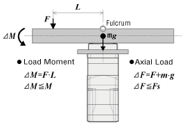
-
Example 2: When an external force F (N) is applied to a position that extends
L (m) vertically from the output flange-mounting surface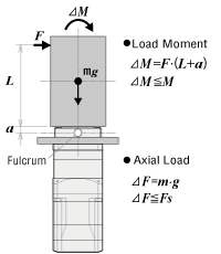
Harmonic Geared Type
| Motor Frame Size | Permissible Axial Load (N) | Permissible Moment Load (N·m) | Constant a (m) |
|---|---|---|---|
| 42 mm | 220 | 5.6 | 0.009 |
| 60 mm | 450 | 11.6 | 0.0114 |
The moment load can be calculated with the following formula.
-
Example 1: When an external force F (N) is applied to a position that extends
L (m) horizontally from the center of the output flange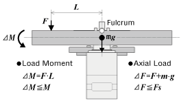
-
Example 2: When external force F (N) is applied to a position that extends in the vertical direction
L (m) from the output flange-mounting surface.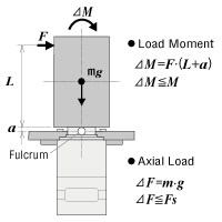
The product names are listed such that the product names are distinguishable.
Cavi e accessori