Electromagnetic Brake Motors World K Series (GU type, former type)
5RK60A-AWMJ
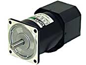
Motor
Dieses Produkt ist derzeit nicht mehr zum Verkauf verfügbar.
| Produktklassifikation | Produktname | Preis | Versand |
|---|---|---|---|
| Motor | 5RK60A-AWMJ | - | Eingestelltes Produkt (Produktionsende 1.4.2015) |
Inklusive
- Motor, Capacitor, Capacitor Cap, Operating Manual
Spezifikationen
Kennlinien
Starting and Braking Characteristics (Reference values)
Starting and Braking Characteristics (Reference values)
Daten-Download
Weitere Spezifikationen
General Specifications
| Item | Specifications |
|---|---|
| Insulation Resistance | After rated operation at normal ambient temperature and humidity, the measurement between the coils and the case is 100 MΩ min. using a 500 VDC megger. |
| Dielectric Strength | No abnormality is observed even with an application of 1.5 kVAC at 50 Hz between the coils and the case for 1 minute after rated operation at normal ambient temperature and humidity. |
| Temperature Rise | After a gearhead or equivalent heat sink* is connected for rated operation at normal ambient temperature and humidity, the measurement value of the winding temperature rise is 80 °C (70 °C maximum for a three-phase 6 W type). using the resistance change method. |
| Thermal Class | 130 (B) |
| Overheat Protective Device | 6 W Type: Impedance protection Other types: Built-in thermal protector (Automatic return type) Open: 130 ± 5 °C, Return: 82 ± 15 °C |
| Operating Ambient Temperature | Single-phase 100 VAC, single-phase 200 VAC, three-phase 200 VAC: -10~+50 °C (Non-freezing) Other voltages: -10~+40 °C (Non-freezing) |
| Operating Ambient Humidity | 85 % max. (Non-condensing) |
| Degree of Protection | 6 W, 15 W, 25 W, 40 W Type: IP20 60 W, 90 W Type: IP40 |
- *Heat sink size (Material: Aluminum)
| Motor Type (Output power) | Size (mm) | Thickness (mm) |
|---|---|---|
| 6 W Type | 115 x 115 | 5 |
| 15 W Type | 125 x 125 | |
| 25 W Type | 135 x 135 | |
| 40 W Type | 165 x 165 | |
| 60 W, 90 W Type | 200 x 200 |
Permissible Radial Load and Permissible Axial Load of Round Shaft Type
Permissible Radial Load
| Motor | Permissible Radial Load N | ||
|---|---|---|---|
| Frame Size □ (mm) | Output Shaft Diameter φ (mm) | From Shaft End 10 mm |
From Shaft End 20 mm |
| 42 | 5 | 40 | - |
| 60 | 6 | 50 | 110 |
| 70 | 6 | 40 | 60 |
| 80 | 8 | 90 | 140 |
| 90 | 10 | 140 | 200 |
| 12 | 240 | 270 | |
Permissible Axial Load
Avoid axial load as much as possible. If an axial load is unavoidable, keep it at half or less of the motor mass.
Kabel und Zubehör
close
close