Electromagnetic Brake Motors World K Series (GU type, former type)
5RK60A-AWMJ
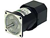
Motor
Dieses Produkt ist derzeit nicht mehr zum Verkauf verfügbar.
| Produktklassifikation | Produktname | Preis | Versand |
|---|---|---|---|
| Motor | 5RK60A-AWMJ | - | Eingestelltes Produkt (Produktionsende 1.4.2015) |
Inklusive
- Motor, Capacitor, Capacitor Cap, Operating Manual
Spezifikationen
Kennlinien
Starting and Braking Characteristics (Reference values)
Daten-Download
Weitere Spezifikationen
General Specifications
| Item | Specifications |
|---|---|
| Insulation Resistance | After rated operation at normal ambient temperature and humidity, the measurement between the coils and the case is 100 MΩ min. using a 500 VDC megger. |
| Dielectric Strength | No abnormality is observed even with an application of 1.5 kVAC at 50 Hz between the coils and the case for 1 minute after rated operation at normal ambient temperature and humidity. |
| Temperature Rise | After a gearhead or equivalent heat sink* is connected for rated operation at normal ambient temperature and humidity, the measurement value of the winding temperature rise is 80 °C (70 °C maximum for a three-phase 6 W type). using the resistance change method. |
| Thermal Class | 130 (B) |
| Overheat Protective Device | 6 W Type: Impedance protection Other types: Built-in thermal protector (Automatic return type) Open: 130 ± 5 °C, Return: 82 ± 15 °C |
| Operating Ambient Temperature | Single-phase 100 VAC, single-phase 200 VAC, three-phase 200 VAC: -10~+50 °C (Non-freezing) Other voltages: -10~+40 °C (Non-freezing) |
| Operating Ambient Humidity | 85 % max. (Non-condensing) |
| Degree of Protection | 6 W, 15 W, 25 W, 40 W Type: IP20 60 W, 90 W Type: IP40 |
- *Heat sink size (Material: Aluminum)
| Motor Type (Output power) | Size (mm) | Thickness (mm) |
|---|---|---|
| 6 W Type | 115 x 115 | 5 |
| 15 W Type | 125 x 125 | |
| 25 W Type | 135 x 135 | |
| 40 W Type | 165 x 165 | |
| 60 W, 90 W Type | 200 x 200 |
Permissible Radial Load and Permissible Axial Load of Round Shaft Type
Permissible Radial Load
| Motor | Permissible Radial Load N | ||
|---|---|---|---|
| Frame Size □ (mm) | Output Shaft Diameter φ (mm) | From Shaft End 10 mm |
From Shaft End 20 mm |
| 42 | 5 | 40 | - |
| 60 | 6 | 50 | 110 |
| 70 | 6 | 40 | 60 |
| 80 | 8 | 90 | 140 |
| 90 | 10 | 140 | 200 |
| 12 | 240 | 270 | |
Permissible Axial Load
Avoid axial load as much as possible. If an axial load is unavoidable, keep it at half or less of the motor mass.
close