Stepper Motors RKII Series
PKE545AC-FC30RA
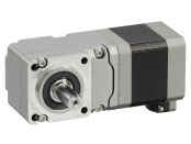
Geared Motor


| Produktklassifikation | Produktname | Preis | Versand |
|---|---|---|---|
| Geared Motor | PKE545AC-FC30RA | 524.00 € | Bitte kontaktieren Sie uns für Details. |
• Specifications and various data of combination products may be shown on the combination product page. Please check the page of the combination product.
Notice: The shipping date refers to the time of dispatch from the warehouse in Düsseldorf/Germany. Shipments with 30 pieces or more will require air freight.
Inklusive
- Motor: Parallel Key
Spezifikationen
Kennlinien
Characteristics Diagram
Abmessungen
Motor
Daten-Download
Weitere Spezifikationen
General Specifications
| Motor | Driver | |||
|---|---|---|---|---|
| Built-in Controller Type | Pulse input type | |||
| Thermal Class | 130 (B) [UL/CSA certified at 105 (A)] |
− | ||
| Insulation Resistance |
100 MΩ or more when a 500 VDC megger is applied between the following places.
|
100 MΩ or more when a 500 VDC megger is applied between the following places.
|
||
| Dielectric Strength |
Sufficient to withstand the following for 1 minute.
|
Sufficient to withstand the following for 1 minute. |
||
|
|
|||
| Operating Environment (when operating) |
Ambient Temperature | -10~+50 °C (Non-freezing) | 0~+55 °C* (Non-freezing) | |
| Ambient Humidity | 85 % max. (Non-condensing) | |||
| Atmosphere | No corrosive gases or dust. No exposure to water, oil or other liquids. |
|||
| Temperature Rise | 5-phase excitation at rated current, 80 °C max. at standstill Temperature rise of winding section at 80 °C or less (resistance change method) |
− | ||
| Degree of Protection | IP20 | IP10 | IP20 | |
- *When installing a heat sink equivalent to an aluminum plate min. 200×200 mm, thickness 2 mm
Note
- Do not measure insulation resistance or perform a dielectric strength test while the motor and driver are connected.
Permissible Radial Load and Permissible Axial Load
Unit: N
| Type | Motor Frame Size |
Type | Gear Ratio | Permissible Radial Load | Permissible Axial Load | ||||
|---|---|---|---|---|---|---|---|---|---|
| Distance From Shaft End [mm] | |||||||||
| 0 | 5 | 10 | 15 | 20 | |||||
| Standard Type | 42 mm | PKE54 | − | 35 | 44 | 58 | 85 | − | 15 |
| 60 mm | PKE56 | 90 | 100 | 130 | 180 | 270 | 30 | ||
| 85 mm | PKE59 | 260 | 290 | 340 | 390 | 480 | 60 | ||
| TS Geared Type | 42 mm | PKE54 | 3.6, 7.2, 10 | 20 | 30 | 40 | 50 | − | 15 |
| 20, 30 | 40 | 50 | 60 | 70 | − | ||||
| 60 mm | PKE56 | 3.6, 7.2, 10 | 120 | 135 | 150 | 165 | 180 | 40 | |
| 20, 30 | 170 | 185 | 200 | 215 | 230 | ||||
| 90 mm | PKE59 | 3.6, 7.2, 10 | 300 | 325 | 350 | 375 | 400 | 150 | |
| 20, 30 | 400 | 450 | 500 | 550 | 600 | ||||
| PS Geared Type | 42 mm | PKE54 | 5 | 70 | 80 | 95 | 120 | - | 100 |
| 7.2 | 80 | 90 | 110 | 140 | - | ||||
| 10 | 85 | 100 | 120 | 150 | - | ||||
| 25 | 120 | 140 | 170 | 210 | - | ||||
| 36 | 130 | 160 | 190 | 240 | - | ||||
| 50 | 150 | 170 | 210 | 260 | - | ||||
| 60 mm | PKE56 | 5 | 170 | 200 | 230 | 270 | 320 | 200 | |
| 7.2 | 200 | 220 | 260 | 310 | 370 | ||||
| 10 | 220 | 250 | 290 | 350 | 410 | ||||
| 25 | 300 | 340 | 400 | 470 | 560 | ||||
| 36 | 340 | 380 | 450 | 530 | 630 | ||||
| 50 | 380 | 430 | 500 | 600 | 700 | ||||
| 90 mm | PKE59 | 5 | 380 | 420 | 470 | 540 | 630 | 600 | |
| 7.2 | 430 | 470 | 530 | 610 | 710 | ||||
| 10 | 480 | 530 | 590 | 680 | 790 | ||||
| 25 | 650 | 720 | 810 | 920 | 1070 | ||||
| 36 | 730 | 810 | 910 | 1040 | 1210 | ||||
| 50 | 820 | 910 | 1020 | 1160 | 1350 | ||||
| Harmonic Geared Type | 42 mm | PKE54 | 50, 100 | 180 | 220 | 270 | 360 | 510 | 220 |
| 60 mm | PKE56 | 320 | 370 | 440 | 550 | 720 | 450 | ||
| 90 mm | PKE59 | 1090 | 1150 | 1230 | 1310 | 1410 | 1300 | ||
| FC Geared Type | 42 mm | PKE54 | 7.2, 10, 20, 30 | 180 | 200 | 220 | 250 | - | 100 |
| 60 mm | PKE56 | 270 | 290 | 310 | 330 | 350 | 200 | ||
- The product names are listed such that the product names are distinguishable.
-
The PS Geared Type has a lifetime of 20,000 hours, when either the permissible radial load or the permissible axial load is applied.
Click here for information about gearhead life
Radial Load and Axial Load
Rotation Direction
This indicates the rotation direction when viewed from the output shaft side.
The rotation direction of the gearhead output shaft relative to the standard type motor output shaft varies depending on the gear type and gear ratio. Please check the following table.
| Type | Gear Ratio | Rotation Direction as Viewed From the Motor Output Shaft Side |
|---|---|---|
| TS Geared Type | 3.6, 7.2, 10 | Same direction |
| 20, 30 | Opposite direction | |
| TH Geared Type Frame size 28 mm |
7.2, 10 | Opposite direction |
| 20, 30 | Same direction | |
| TH Geared Type Frame size 42 mm, 60 mm, 90 mm |
3.6, 7.2, 10 | Same direction |
| 20, 30 | Opposite direction | |
| SH Geared Type Frame size 28 mm |
7.2, 36 | Same direction |
| 9, 10, 18 | Opposite direction | |
| SH Geared Type Frame size 42 mm, 60 mm |
3.6, 7.2, 9, 10 | Same direction |
| 18, 36 | Opposite direction | |
| SH Geared Type Frame size 90 mm |
3.6, 7.2, 9, 10, 18 | Same direction |
| 36 | Opposite direction | |
| CS Geared Type | 5, 10, 15, 20 | Same direction |
|
FC Geared Type PS Geared Type PN Geared Type HPG Geared Type |
Overall gear ratio | Same direction |
| Harmonic Geared Type | 30, 50, 100 | Opposite direction |
close
close