Compact Electric Cylinders DRLII Series
DRL42G-04A8PN-KB
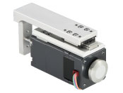
Actuator/Control Circuit
Dieses Produkt ist derzeit nicht mehr zum Verkauf verfügbar.
| Produktklassifikation | Produktname | Preis | Versand |
|---|---|---|---|
| Actuator / Control Circuit | DRL42G-04A8PN-KB | - | Eingestelltes Produkt (Produktionsende 31.3.2022) |
Inklusive
- Actuator, Control Circuit, Power Supply Connector (CN1), Connectors for Actuator Connection (CN2), I/O Signal Connector (CN3), Operating Manual
Spezifikationen
Abmessungen
Actuator
Weitere Spezifikationen
General Specifications
| Specifications | Actuator Section | Driver | ||
|---|---|---|---|---|
| Built-in Controller | Pulse Input | |||
| Thermal Class | 130(B) [UL/CSA Standard obtainment is certified with 105(A)] |
- | - | |
| Insulation Resistance | 100 MΩ or more when a 500 VDC megger is applied between the motor windings and the case. |
100 MΩ or more when a 500 VDC megger is applied between the following places:
|
||
| Dielectric Strength |
No abnormality is observed when the following is applied between the motor windings and the case of the motor for 1 minute.
|
- | - | |
| Operating Environment (When operating) |
Ambient Temperature | 0~40 °C* (non-freezing) *DRL20V, DRL28V can range from 5~40 °C. | ||
| Ambient Humidity | 85 % max. (Non-condensing) | |||
| Atmosphere | No corrosive gases or dust. No exposure to water, oil or other liquids. | |||
| Degree of Protection | IP00 | IP10 | IP20 | |
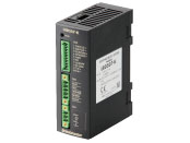
Driver Circuit Specifications
| Driver Type | Built-in Controller | Pulse Input | ||
|---|---|---|---|---|
| Driver Product Name | LRD503-KD, LRD507-KD, LRD514-KD | LRD503-K, LRD507-K, LRD514-K | ||
| Power Supply Input | 24 VDC±10 % | LRD503-KD: 0.7 A LRD507-KD: 1.4 A LRD514-KD: 2.5 A |
24 VDC±10 % | LRD503-K: 0.7 A LRD507-K: 1.4 A LRD514-K: 2.5 A |
| Maximum Input Pulse Frequency | - | Line Driver Output by Host Controller: 500 kHz (When the pulse duty is 50 %) Open-Collector Output by Host Controller: 250 kHz (When the pulse duty is 50 %) |
||
| Input Signals | Input Mode: Photocoupler input | Input Mode: Photocoupler input | ||
| CW Pulse Signal (Pulse signal) CW (forward) direction operation command pulse signal (Operation command pulse signal when 1-pulse input mode is used) Negative logic pulse input, pulse width 1 μs or more, rise and fall time 2 μs or less, pulse duty 50 % or less When pulse input is turned from "ON" to "OFF," the screw shaft moves 1 step in the forward direction. |
||||
| CCW pulse signal (travel direction signal) CCW (backward) direction operation command pulse signal (when in 1-pulse input mode, travel direction signal photocoupler "ON": CW, Photocoupler "OFF": CCW) Negative logic pulse input, pulse width 1 μs or more, rise and fall time 2 μs or less, pulse duty 50 % or less When pulse input is turned from "ON" to "OFF," the screw shaft moves 1 step in the backward direction. |
||||
| All Windings Off Signal When the photocoupler is "ON," the output current to the actuator is turned OFF. When the photocoupler is "OFF," the output current to the actuator is turned ON. |
||||
| Step Angle Select Input Signal Selects the step angle setting switch when the photocoupler is "OFF" and the basic step angle when the photocoupler is "ON." |
||||
| Automatic Current Cutback Release Signal When the photocoupler is "ON," the automatic current cutback function for when the actuator stops is canceled. When the photocoupler is "OFF," the automatic current cutback function is activated when the actuator stops (after approx. 100 ms). |
||||
| Output Signals | Output Format: Photocoupler and Open-Collector Output Line Driver Output PLS-OUT, DIR-OUT |
Output Format: Photocoupler and open-collector output | ||
| Excitation Timing Signal This signal is output when the excitation sequence is step "0." (Photocoupler: ON) For a Resolution of 1: output once every 10 pulses For a Resolution of 10: output once every 100 pulses |
||||
| Number of Positioning Data Sets | 63 points | - | ||
| Positioning Operation | Single, linked, linked 2, sequential | - | ||
| Other operations | JOG operation, return-to-home operation, continuous operation, test operation | - | ||
| Control Module OPX-2A | ○ | - | ||
| Support Software MEXE02 | ○ | - | ||
| Function | Smooth drive, automatic current cutback, step angle switching, pulse input mode switching (pulse input only), all windings off, excitation timing | |||
| Cooling Method | Natural Cooling Method | |||
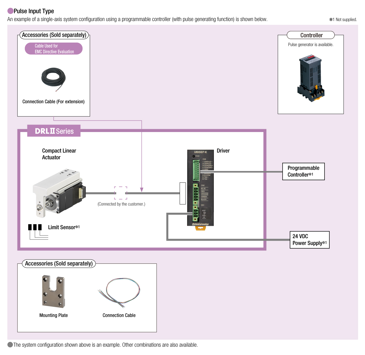
Systemkonfiguration
Kabel und Zubehör
close