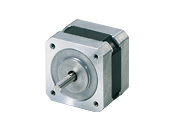
Stepper Motors FineStep CFKII Series
CFK545AP2
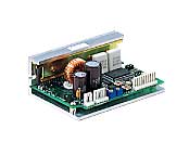
Motor/Control Circuit
Dieses Produkt ist derzeit nicht mehr zum Verkauf verfügbar.
| Produktklassifikation | Produktname | Preis | Versand |
|---|---|---|---|
| Motor / Control Circuit | CFK545AP2 | 488.00 € | Eingestelltes Produkt (Produktionsende 31.3.2019) |
Inklusive
- Motor, Control Circuit, Connector Housing, Contact, Operating Manual
Spezifikationen
Daten-Download
Weitere Spezifikationen
Circuit Specifications
| Input Signals | Input Mode |
Photocoupler Input
Pulse input: input resistance 220 Ω, input current 10~20 mA
Signal input: input resistance 470 Ω, input current 10~15 mA photocoupler "ON": +4.5~5 V, photocoupler "OFF": 0~+1 V (terminal voltage) |
|---|---|---|
| CW Pulse Signal (Pulse signal) |
CW direction operation command pulse signal (operation command pulse signal when 1-pulse input mode) Pulse width 1 μs min. rise and fall time 2 μs max. Pulse duty 50 % max. When the pulse input is turned from "ON" to "OFF," the motor rotates 1 step. Maximum input pulse frequency: 500 kHz (at 50 % pulse duty) Negative logic pulse input |
|
| CCW Pulse Signal (Rotation direction signal) |
CCW direction movement command pulse signal (for 1-pulse input mode, rotation direction signal Photocoupler ON: CW, Photocoupler OFF: CCW) Pulse width 1 μs min., rise/fall time 2 μs max., pulse duty 50 % max. When the pulse input is turned from "ON" to "OFF," the motor rotates 1 step. Maximum input pulse frequency: 500 kHz (at 50 % pulse duty) Negative logic pulse input |
|
| Step Angle Select Input Signal | When the photocoupler is "OFF," DATA1 is selected; when the photocoupler is "ON," DATA2 is selected. | |
| All Windings Off Signal | When the photocoupler is "ON," the output current to the motor is turned "OFF," and the motor shaft can be turned by external force. When the photocoupler is "OFF," output current to the motor is turned "ON." |
|
| Output Signals | Output Mode | Photocoupler and Open-Collector Output External Use Conditions: 24 VDC max., 10 mA max. |
| Excitation Timing Signal | This signal is output when the excitation sequence is step "0." 0.72˚/step (number of divisions 1): output once per 10 pulses, 0.072˚/step (number of divisions 10): output once per 100 pulses |
|
| Function | Step angle switching, pulse input mode switching, current check switch, automatic current cutback | |
| Cooling Method | Natural cooling method | |
General Specifications
| Specifications | Motor | Driver | |
|---|---|---|---|
| Insulation Class | Class B (130 °C) | - | |
| Insulation Resistance | 100 MΩ or more when a 500 VDC megger is applied between the motor windings and the case under normal ambient temperature and humidity. | - | |
| Dielectric Strength |
Under normal ambient temperature and humidity, no abnormalities were observed even with 1.0 kV * at 50 Hz and 60 Hz applied between the windings and the case of the motor for 1 minute.
|
- | |
| Operating Environment (when operating) |
Ambient Temperature | -10~+50 °C (non-freezing) | 0~+40 °C (Non-freezing) |
| Ambient Humidity | 85 % max. (Non-condensing) | ||
| Atmosphere | No corrosive gases or dust. No exposure to water, oil or other liquids. | ||
| Temperature Rise | 5-phase excitation at rated current, coil temperature rise to 80 °C max. at standstill (Resistance change method) |
- | |
| Stop position accuracy*1 | ±3 arcmin (±0.05°) CFK52 ±5 arcmin (±0.084°) CFK51 ±10 arcmin (±0.17°) |
- | |
| Shaft Runout | 0.05 T.I.R. (mm)*4 | - | |
| Radial Play*2 | 0.025 mm Max. (Load 5 N) | - | |
| Axial Play*3 | 0.075 mm Max. (Load 10 N) | - | |
| Concentricity of Installation Pilot to the Shaft | 0.075 T.I.R. (mm)*4 | - | |
| Perpendicularity of mounting surface to the shaft | 0.075 T.I.R. (mm)*4 | - | |
- *1
- This is the value at full step and no load (Varies depending on the size of the load).
- *2
- Radial Play: Displacement in shaft position in the radial direction when a 5 N load is applied perpendicular to the tip of the motor shaft.
- *3
- Axial Play: Displacement in shaft position in the axial direction when a 10 N load is applied to the motor shaft in the axial direction.
- *4
- T.I.R. (Total Indicator Reading): The total dial gauge reading when the measurement section is rotated 1 revolution centered on the reference axis center.
Note
- Do not measure insulation resistance or perform a dielectric strength test while the motor and driver are connected.
Permissible Radial Load and Permissible Axial Load
| Product Name | Permissible Radial Load | Permissible Axial Load | ||||
|---|---|---|---|---|---|---|
| Distance From Shaft End [mm] | ||||||
| 0 | 5 | 10 | 15 | 20 | ||
| CFK513P□P2 | 12 | 15 | - | - | - | Self-weight of motor max. |
| CFK523□P2 CFK525□P2 |
25 | 34 | 52 | - | - | |
| CFK543□P2 CFK544□P2 CFK545□P2 |
20 | 25 | 34 | 52 | - | |
| CFK564□P2 CFK566□P2 CFK569□P2 |
63 | 75 | 95 | 130 | 190 | |
| CFK566H□P2 CFK569H□P2 |
63 | 75 | 95 | 130 | 190 | |
| CFK596H□P2 CFK599H□P2 CFK5913H□P2 |
260 | 290 | 340 | 390 | 480 | |
- Either A or B indicating the motor shaft type is specified where the box □ is located in the product name.
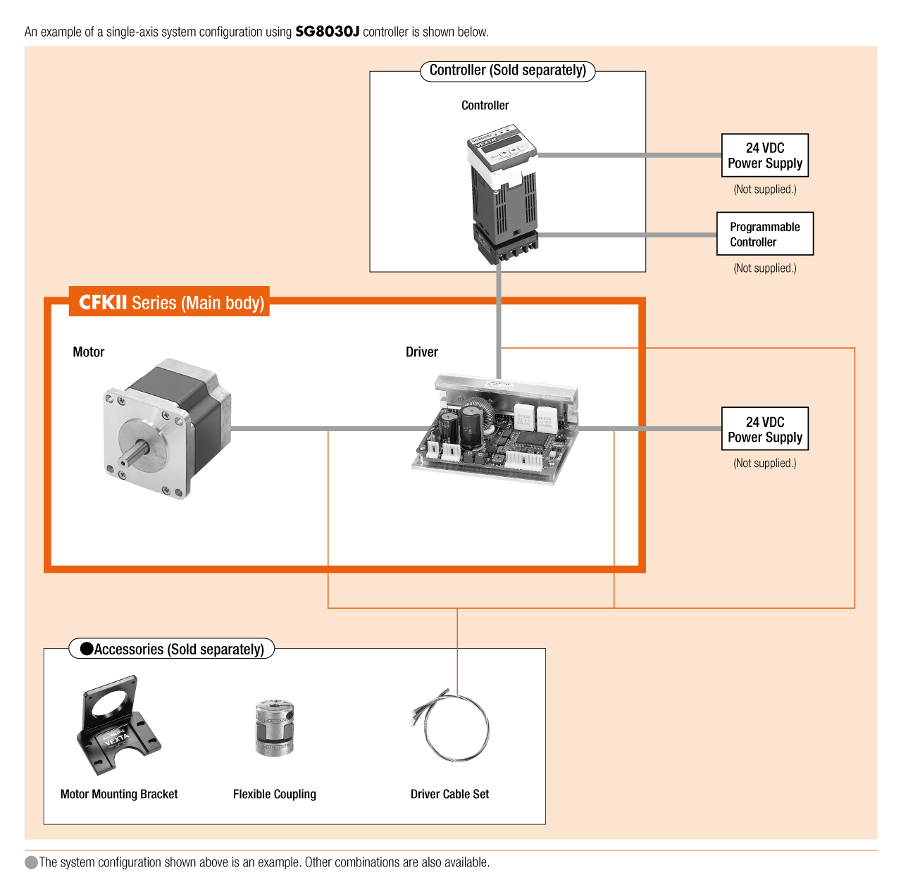
Systemkonfiguration
close