AC Speed Control Motors BSM Series
BSM315-011
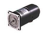
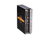
Motor/Control Circuit
Dieses Produkt ist derzeit nicht mehr zum Verkauf verfügbar.
| Produktklassifikation | Produktname | Preis | Versand |
|---|---|---|---|
| Motor / Control Circuit | BSM315-011 | - | Eingestelltes Produkt (Produktionsende 1.4.2016) |
Inklusive
- Motor and Driver Package: Motor, Capacitor, External Speed Potentiometer, Control Circuit, Operating Manual
Spezifikationen
Abmessungen
Motor
Weitere Spezifikationen
General Specifications (Motor)
| Item | Specifications |
|---|---|
| Insulation Resistance | After rated operation at normal ambient temperature and humidity, the value measured with a 500 VDC megger between the motor windings and the case is 100 MΩ min. |
| Dielectric Strength | After rated operation at normal ambient temperature and humidity, no abnormality is observed even if 50 Hz, 1.5 kVAC is applied between the motor windings and the case for 1 minute. |
| Temperature Rise | The value measured by the thermometer method after rated operation is 60 °C max. |
| Thermal Class | 120(E) |
| Operating Ambient Temperature | -10~+50°C (Non-freezing) |
| Operating Ambient Humidity | 85 % max. (Non-condensing) |
Control Circuit Specifications
| Item | MSP301N | MSP302N |
|---|---|---|
| Power Supply Input | Single-Phase 100 VAC±10% 50/60 Hz | Single-Phase 200 VAC±10% 50/60 Hz |
| Functions | Speed control, non-contact instantaneous stop, non-contact bidirectional rotation, non-contact rotation speed switching, slow start/slow down, electromagnetic brake/electronic brake interlocking, non-contact electromagnetic brake control, electromagnetic brake free | |
| Control Power Supply | 24 VDC±10% or 5 VDC±10% min. 0.1 A | |
| Control Input | Signal Input: CW/CCW/FREE/SPEED SET Photocoupler Input External Contact Capacity: DC24V 40mA Speed Setting Signal (Analog Input) Speed Potentiometer (0~20 kΩ) or Voltage Signal (0~5 VDC) |
|
| Variable Speed Range | 50 Hz: 90~1400 r/min 60 Hz: 90~1700 r/min | |
| Insulation Resistance | The value measured with a 500 VDC megger between the power supply input terminal and FG, between the signal input terminal and FG, and between the power supply input terminal and signal input terminal is min. 100 MΩ. | |
| Dielectric Strength | No abnormality is observed even if 50 Hz, 1.5 kV is applied between the power supply input terminal and FG, between the signal input terminal and FG, or between the power supply input terminal and signal input terminal for 1 minute. | |
| Operating Ambient Temperature | 0∼+40 °C (Non-freezing) | |
| Operating Ambient Humidity | 85 % max. (Non-condensing) | |
Note
-
No insulation resistance measurement or dielectric strength test while the motor and speed control pack are connected.
Permissible Radial Load and Permissible Axial Load of Round Shaft Type
Permissible Radial Load
| Motor | Permissible Radial Load N | ||
|---|---|---|---|
| Frame Size □ (mm) | Output Shaft Diameter φ (mm) | From Shaft End 10 mm |
From Shaft End 20 mm |
| 42 | 5 | 40 | - |
| 60 | 6 | 50 | 110 |
| 70 | 6 | 40 | 60 |
| 80 | 8 | 90 | 140 |
| 90 | 10 | 140 | 200 |
| 12 | 240 | 270 | |
Permissible Axial Load
Avoid axial load as much as possible. If an axial load is unavoidable, keep it at half or less of the motor mass.
close