Brushless Motors BLH Series (Former type)
BLH450K-30
Gearhead / Motor / Control Circuit
Dieses Produkt ist derzeit nicht mehr zum Verkauf verfügbar.
| Produktklassifikation | Produktname | Preis | Versand |
|---|---|---|---|
| Gearhead / Motor / Control Circuit | BLH450K-30 | - | Eingestelltes Produkt (Produktionsende 31.3.2020) |
Inklusive
- Motor, Control Circuit, Gearhead, I/O Signal Cable, Power Supply Cable, Mounting Screws, Parallel Key, Operating Manual
Spezifikationen
Daten-Download
Weitere Spezifikationen
Common Specifications
| Item | Specifications |
|---|---|
| Speed Setting Methods |
Set 1 method from the following.
|
| Acceleration Time and Deceleration Time | 0.5~10 seconds 3000 r/min no-load setting forBLH015 type, 2500 r/min no-load setting for BLH230, BLH450, BLH5100 types (However, this may vary depending on the size of the load.) Common setting using acceleration and deceleration time potentiometer: |
| Multi-Speed Setting Methods | 2-Speed 2-speed 1 speed by 1 internal speed potentiometer and 1 speed by external speed potentiometer, or external DC voltage (0~5 VDC) |
| Input Signals | C-MOS Negative Logic Input Method Operated by Internal Power Supply Common to start/stop input, run/brake input, rotation direction switching input, speed setting method selection input and alarm reset input |
| Output Signals | Open-collector output Operated by external power supply Operating conditions 26.4 VDC max. 10 mA max. Common to alarm output and speed output |
| Protective Functions* |
When the following protective functions are activated, the motor will coast to a stop, and the ALARM output will be turned off. The alarm LED of the driver blinks the number of times indicated in parentheses ( ).
|
| Maximum Extension Distance | Between motor and driver 2 m (when an accessory connection cable is used) |
| Time Rating | Continuous |
- *The BLH Series cannot control the speed control of the motor in applications where the motor side is turned from the load side, such as gravitational operation.
When a load exceeding the permissible load inertia value is driven, or when gravitational operation is performed, the overvoltage protective function works to bring the motor to a coasting stop.
General Specifications
| Item | Motor | Driver | |
|---|---|---|---|
| Insulation Resistance | 100 MΩ or more when a 500 VDC megger is applied between the windings and the case after continuous operation under normal ambient temperature and humidity. |
After continuous operation at normal ambient temperature and humidity, the value measured with a 500 VDC megger between the power supply input and the heat sink is min. 100 MΩ. |
|
| Dielectric Strength | No abnormality is observed even with an application of 0.5 kVAC at 50 Hz between the coils and the case for 1 minute after continuous operation at normal ambient temperature and humidity. |
After continuous operation at normal ambient temperature and humidity, no abnormality is observed when 50 Hz, 0.5 kVAC is applied between the power supply input and the heat sink for 1 minute. |
|
| Temperature Rise | After continuous operation at normal temperature and humidity, the measured value using the thermocouple method is 50 °Cmax. for the temperature rise of the coils and 40 °C max. *1for the temperature rise on the case surface. |
After continuous operation at normal ambient temperature and humidity, the measurement value of the temperature rise of the heat sink is 50 °C max. using the thermocouple method. |
|
| Operating Environment | Ambient Temperature | 0~+50°C (Non-freezing) | |
| Ambient Humidity | 85 % max. (Non-condensing) | ||
| Altitude | Up to 1000 m above sea level | ||
| Atmosphere | Cannot be used in special environments such as corrosive gas, no dust, radioactive materials, magnetic fields, or vacuums | ||
| Vibration | Not subject to continuous vibration or excessive shock In conformance with JIS C 60068-2-6, "Sine-wave vibration test method" Frequency Range: 10~55 Hz, Half Amplitude: 0.15 mm, Sweep Direction: 3 directions (X, Y, Z), Number of Sweeps: 20 times |
||
| Storage Conditions*2 | Ambient Temperature | -25~+70°C (Non-freezing) | |
| Ambient Humidity | 85 % max. (Non-condensing) | ||
| Altitude | Up to 3000 m above sea level | ||
| Thermal Class | UL/CSA Standards: 105 (A), EN Standards: 120 (E) | − | |
| Degree of Protection | IP40 | IP00 | |
- *1
- AAttach round shaft types to a heat sink (Material: aluminum) of one of the following sizes to maintain a motor case surface temperature of 90 °C max. (Except for the 15 W Type.)
30 W Type: 115x115 mm, 5 mm thickness
50 W Type: 135x135 mm, 5 mm thickness
100 W Type: 200x200 mm, 5 mm thickness - *2
- The value for storage condition applies to short periods such as the period during transport.
Note
- Do not measure insulation resistance or perform a dielectric strength test the motor and driver are connected.
Permissible Radial Load and Permissible Axial Load
Geared Type/Combination Type With a Parallel Shaft Gearhead
| Product Name | Gear Ratio | Permissible Radial Load | Permissible Axial Load N |
|
|---|---|---|---|---|
| 10 mm From Shaft End N |
20 mm From Shaft End N |
|||
| BLH015K-□ | 5, 10, 15, 20 30, 50, 100 |
50 | − | 30 |
| BLH230K-□ | 5 | 100 | 150 | 40 |
| 10, 15, 20 | 150 | 200 | ||
| 30, 50, 100, 200 | 200 | 300 | ||
| BLH450K-□ | 5 | 200 | 250 | 100 |
| 10, 15, 20 | 300 | 350 | ||
| 30, 50, 100, 200 | 450 | 550 | ||
| BLH5100K-□ | 5 | 300 | 400 | 150 |
| 10, 15, 20 | 400 | 500 | ||
| 30, 50, 100, 200 | 500 | 650 | ||
Combination type with a hollow shaft flat gearhead
| Product Name | Gear Ratio | Permissible Radial Load | Permissible Axial Load N |
|
|---|---|---|---|---|
| 10 mm From the Gearhead Mounting Surface N |
20 mm From the Gearhead Mounting Surface N |
|||
| BLH230K-□FR | 5, 10 | 450 | 370 | 200 |
| 15, 20, 30, 50, 100, 200 | 500 | 400 | ||
| BLH230K-□FR | 5, 10 | 800 | 660 | 400 |
| 15, 20, 30, 50, 100, 200 | 1200 | 1000 | ||
| BLH5100K-□FR | 5, 10 | 900 | 770 | 500 |
| 15, 20 | 1300 | 1110 | ||
| 30, 50, 100, 200 | 1500 | 1280 | ||
Round Shaft Type
| Product Name | Permissible Radial Load | Permissible Axial Load | |
|---|---|---|---|
| 10 mm From Shaft End N |
20 mm From Shaft End N |
||
| BLH015K-A | 50 | − | Half of the motor mass or less |
| BLH230K-A | 70 | 100 | |
| BLH450K-A | 120 | 140 | |
| BLH5100K-A | 160 | 170 | |
Systemkonfiguration
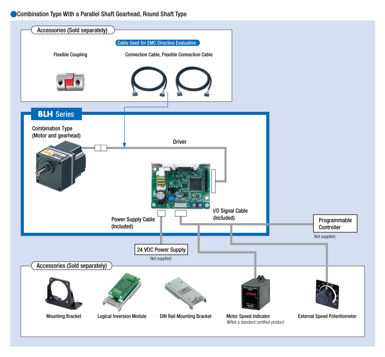
Kabel und Zubehör
close