Inverters BHF Series
BHF62CT-A
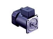
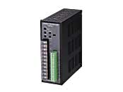
Motor/Control Circuit
Dieses Produkt ist derzeit nicht mehr zum Verkauf verfügbar.
| Produktklassifikation | Produktname | Preis | Versand |
|---|---|---|---|
| Motor / Control Circuit | BHF62CT-A | - | Eingestelltes Produkt (Produktionsende 31.3.2019) |
Inklusive
- Motor, Control Circuit, Mounting Bracket for Control Circuit (with Screws), Operating Manual
Spezifikationen
Daten-Download
Weitere Spezifikationen
Common Specifications
| Item | Specifications |
|---|---|
| Slow Start/ Slow Down |
Approx. 0.1~25 seconds (at 1000 r/min) |
| Speed Setting Methods | Set 1 method from the following. - Internal Speed Potentiometer (1 pc) - External Speed Potentiometer (20kΩ 1/4W) - DC Voltage Control (0~5 VDC) |
| Input Signals | Photocoupler Input Method, Input Resistance 2.3kΩ, Operates with Internal Power Supply 12VDC Common to CW/CCW, speed setting input selection, slow down, alarm reset |
| Output Signals | Open-Collector Output Operated by External Power Supply Usage Conditions 26.4 VDC 10 mA max. Speed Monitor Output (12P/R), Alarm Output |
| Protective Functions |
When the following protective functions are activated,
|
| Maximum Extension Distance | 50 m between motor and inverter |
| Time Rating | Continuous |
General Specifications
| Item | Motor | Inverter |
|---|---|---|
| Insulation Resistance | After rated operation at normal ambient temperature and humidity, the measurement between the coils and the case is 100 MΩ min. using a 500 VDC megger. | After rated operation at normal ambient temperature and humidity, the value measured with a 500 VDC megger between the power supply input terminal and the protective earth terminal, and between the power supply input terminal and the I/O signal terminal is min. 100 MΩ. |
| Dielectric Strength | No abnormality is observed even with an application of 1.5 kVAC at 50 Hz between the coils and the case for 1 minute after rated operation at normal ambient temperature and humidity. | After rated operation at normal ambient temperature and humidity, no abnormality is observed when 50 Hz or 60 Hz, 1.5 kVAC is applied between the power supply input terminal and the protective earth terminal for 1 minute, and 50 Hz or 60 Hz, 3 kVAC is applied between the power supply input terminal and the I/O terminal for 1 minute. |
| Temperature Rise | After rated operation under normal ambient temperature and humidity, the winding temperature rise measured by the resistance change method with the gearhead or equivalent heat sink * attached to the motor is 70 °C max. | − |
| Operating Temperature Range | -10~+40°C (at 100 V and 200 V: -10~+50°C) (Non-freezing) | 0∼+50°C (Non-freezing) |
| Operating Humidity Range | 85 % max. (Non-condensing) | 85 % max. (Non-condensing) |
| Thermal Class | 130(B) | - |
| Degree of Protection | IP54 (Excluding mounting surface of the Round Shaft Type.) | IP10 |
- *Heat Sink Size: 230×230 mm, 5 mm thickness (Material: Aluminum)
Permissible Radial Load and Permissible Axial Load of Round Shaft Type
Permissible Radial Load
| Motor | Permissible Radial Load N |
||
|---|---|---|---|
| Frame Size □ (mm) | Output Shaft Diameter φ (mm) | From Shaft End 10 mm |
From Shaft End 20 mm |
| 104 | 14 | 320 | 350 |
Permissible Axial Load
Avoid axial load as much as possible. If an axial load is unavoidable, keep it at half or less of the motor mass.
Kabel und Zubehör
close