Induction Motors
4IK25AB-3.6SS
Combi geared motor
Dieses Produkt ist derzeit nicht mehr zum Verkauf verfügbar.
| Produktklassifikation | Produktname | Preis | Versand |
|---|---|---|---|
| Combi geared motor | 4IK25AB-3.6SS | - | Eingestelltes Produkt (Produktionsende 1.4.2015) |
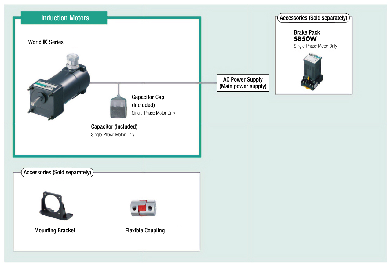
Inklusive
- Motor, Capacitor, Capacitor Cap, Gearhead, Mounting Screws, Parallel Key, Operating Manual
Spezifikationen
Abmessungen
Capacitor
Daten-Download
Weitere Spezifikationen
General Specifications
| Item | Specifications |
|---|---|
| Insulation Resistance | After rated operation at normal ambient temperature and humidity, the measurement between the coils and the case is 100 MΩ min. using a 500 VDC megger. |
| Dielectric Strength | After continuous rated operation at normal ambient temperature and humidity, no abnormalities were observed even with an application of 1.5 kV at 50 Hz or 60 Hz between the coils and the case for 1 minute. |
| Temperature Rise | A gearhead or equivalent heat sink* is connected to the motor and the winding temperature rise is measured at 80 °C max. using the resistance change method after continuous rated operation under normal ambient temperature and humidity. (Three-Phase type is 70 °C max.) |
| Thermal Class | 130 (B) |
| Overheat Protective Device |
Thermal protector operating temperature Open: 130±5 °C, Return: 90±15 °C (normally closed) |
| Operating Ambient Temperature | Single-phase 100 V, single-phase 200 V, three-phase 200 V: -10~+50 °C (Non-freezing) Other voltages: -10~+40 °C (Non-freezing) |
| Operating Ambient Humidity | 85 % max. (Non-condensing) |
| Degree of Protection | IP65 (Excluding mounting surface of the round shaft type) |
- * Heat Sink Size (Material: Aluminum)
| Motor Type (Output Power) | Size (mm) | Thickness (mm) |
|---|---|---|
| 6 W type | 115 x 115 | 5 |
| 15 W type | 125 x 125 | |
| 25 W type | 135 x 135 | |
| 40 W type | 165 x 165 |
Permissible Radial Load and Permissible Axial Load of Gearhead
| Product Name | Gear Ratio | Maximum Permissible Torque N·m |
Permissible Radial Load N | Permissible Axial Load N |
|
|---|---|---|---|---|---|
| From Shaft End 10 mm |
From Shaft End 20 mm |
||||
| 2GN□S | 3~18 | 3.0 | 50 | 80 | 30 |
| 25~180 | 120 | 180 | |||
| 3GN□S | 3~18 | 5.0 | 80 | 120 | 40 |
| 25~180 | 150 | 250 | |||
| 4GN□S | 3~18 | 8.0 | 100 | 150 | 50 |
| 25~180 | 200 | 300 | |||
| 5GN□S | 3~18 | 10 | 250 | 350 | 100 |
| 25~180 | 300 | 450 | |||
Systemkonfiguration
Kabel und Zubehör
close