Stepper Motors PKP Series/PK Series (2-Phase)
PKP242D23A2H100R3FL
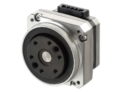
Motor


Connection Cable (Motor~Control Circuit)
Encoder Connection Cable
| Produktklassifikation | Produktname | Preis | Versand |
|---|---|---|---|
| Motor | PKP242D23A2H100R3FL | 832.00 € | Up to 10 pcs Estimated Ship 7weeks |
Notice: The shipping date refers to the time of dispatch from the warehouse in Düsseldorf/Germany. Shipments with 30 pieces or more will require air freight.
Inklusive
- Motor: None
Spezifikationen
Kennlinien
Abmessungen
Daten-Download
Weitere Spezifikationen
Motor General Specifications
| Item | Specification | |
|---|---|---|
| Operating Environment (when operating) |
Ambient Temperature | -10~+50 °C (Non-freezing) 0~+40 °C for Flat Harmonic Gearhead Type and Harmonic Gearhead Type (Non-freezing) |
| Ambient Humidity | 85 % max. (Non-condensing) | |
| Atmosphere | No corrosive gases or dust No exposure to water, oil or other liquids. | |
| Temperature Rise | Winding temperature rise 80 °C max. (Based on Oriental Motor's internal measurement conditions) | |
| Stop position accuracy*1 | ±3 arc minute (±0.05˚) [PKP21□, PKP242, PKP262is ±5 arcmin (±0.083°), PK26□J, PK26□JDis ±2 arcmin (±0.034°)] |
|
| Shaft Runout | 0.05 T.I.R. (mm) *4 *5 | |
| Radial Play*2 | 0.025 mm Max. (Load 5 N) [PKP203 Load 2.5 N] |
|
| Axial Play*3 | 0.075 mm Max (Load 10 N) [PKP203・PKP21□ Load 1 N, PKP22□, PKP242, PKP262 Load 2.5 N] |
|
| Concentricity of Installation Pilot to the Shaft | 0.075 T.I.R. (mm)*4 | |
| Perpendicularity of mounting surface to the shaft | 0.075 T.I.R. (mm)*4 | |
- *1
- This is the value at full step and no load (Varies depending on the size of the load).
- *2
- Radial Play: Displacement in shaft position in the radial direction when a 5 N load (PKP203 Load 2.5 N) is applied perpendicular to the tip of the motor shaft.
- *3
- Axial Play: Displacement in shaft position in the axial direction when a 10 N load (PKP203, PKP21□ Load 1 N, PKP22□, PKP242, PKP262 Load 2.5 N) is applied to the motor shaft in the axial direction.
- *4
- T.I.R. (Total Indicator Reading): The total dial gauge reading when the measurement section is rotated 1 revolution centered on the reference axis center.
- *5
- PKP244P has 0.025 T.I.R. (mm)
Encoder Specifications
| Encoder Product Name | R3E | R3F | R3G | R3J | R3EL | R3FL | R3GL | R3JL |
|---|---|---|---|---|---|---|---|---|
| Resolution (P/R) | 200 | 400 | 500 | 1000 | 200 | 400 | 500 | 1000 |
| Angular Accuracy | ±0.36° (converted value at motor output shaft) | |||||||
| Output Circuit Type | Voltage output | Line Driver Output* | ||||||
| Output Mode | Incremental | |||||||
| Output Signals | Phase A, Phase B, Phase Z (3ch) | |||||||
| Power Supply Voltage | 5 VDC±10 % | |||||||
| Current | 45 mA max. | 30 mA max. | ||||||
- *26C31 or Equivalent
Permissible Moment Load and Permissible Axial Load
When an eccentric (uneven) load is applied to the output flange-mounting surface, the load moment acts on the bearing.
Use the following formula to check whether the axial load and moment load are within specification values.
| Type | Gear Ratio | Permissible Axial Load (N) | Permissible Moment Load (N·m) | Constant a (m) |
|---|---|---|---|---|
| PKP242 | 50, 100 | 200 | 8.5 | 0.0129 |
| PKP262 | 450 | 5.0 | 0.0095 | |
| PKP262-H□S | 450 | 10.1 | 0.0140 |
The permissible moment load and permissible axial load can be calculated by the following formulas.
-
Example 1:When an external force F (N) is applied to a position that extends L (m) horizontally from the center of the output flange
-
Example 2:When an external force F (N) is applied to a position that extends L (m) vertically from the output flange-mounting surface
Inner Wiring Diagram of Motor
Rotation Direction
This indicates the rotation direction when viewed from the output shaft side.
The rotation direction of the gearhead output shaft relative to the standard type motor output shaft varies depending on the gear type and gear ratio. Please check the following table.
| Type | Gear Ratio | Rotation Direction as Viewed From the Motor Output Shaft Side |
|---|---|---|
| TS Geared Type | 3.6, 7.2, 10 | Same direction |
| 20, 30 | Opposite direction | |
| TH Geared Type Frame size 28 mm |
7.2, 10 | Opposite direction |
| 20, 30 | Same direction | |
| TH Geared Type Frame size 42 mm, 60 mm, 90 mm |
3.6, 7.2, 10 | Same direction |
| 20, 30 | Opposite direction | |
| SH Geared Type Frame size 28 mm |
7.2, 36 | Same direction |
| 9, 10, 18 | Opposite direction | |
| SH Geared Type Frame size 42 mm, 60 mm |
3.6, 7.2, 9, 10 | Same direction |
| 18, 36 | Opposite direction | |
| SH Geared Type Frame size 90 mm |
3.6, 7.2, 9, 10, 18 | Same direction |
| 36 | Opposite direction | |
| CS Geared Type | 5, 10, 15, 20 | Same direction |
|
FC Geared Type PS Geared Type PN Geared Type HPG Geared Type |
Overall gear ratio | Same direction |
| Harmonic Geared Type | 30, 50, 100 | Opposite direction |
Standards
Regulations and Standards Materials
Documents about compliance with regulations and standards can be downloaded from the "Data Download" tab on the product details page.
(The types of files available for download vary by product.)
Explanations of the Global Laws, Regulations and Standards can be found here.
Information about our compliance with regulations and standards for each of our product series can be found here.
Hazardous Substances
The product does not contain any substances (10 substances) exceeding the regulation values of the RoHS Directive (2011/65/EU, 2015/863/EU).
For more information about compliance with regulations on chemical substances in Oriental Motor's Products, click here.
Systemkonfiguration
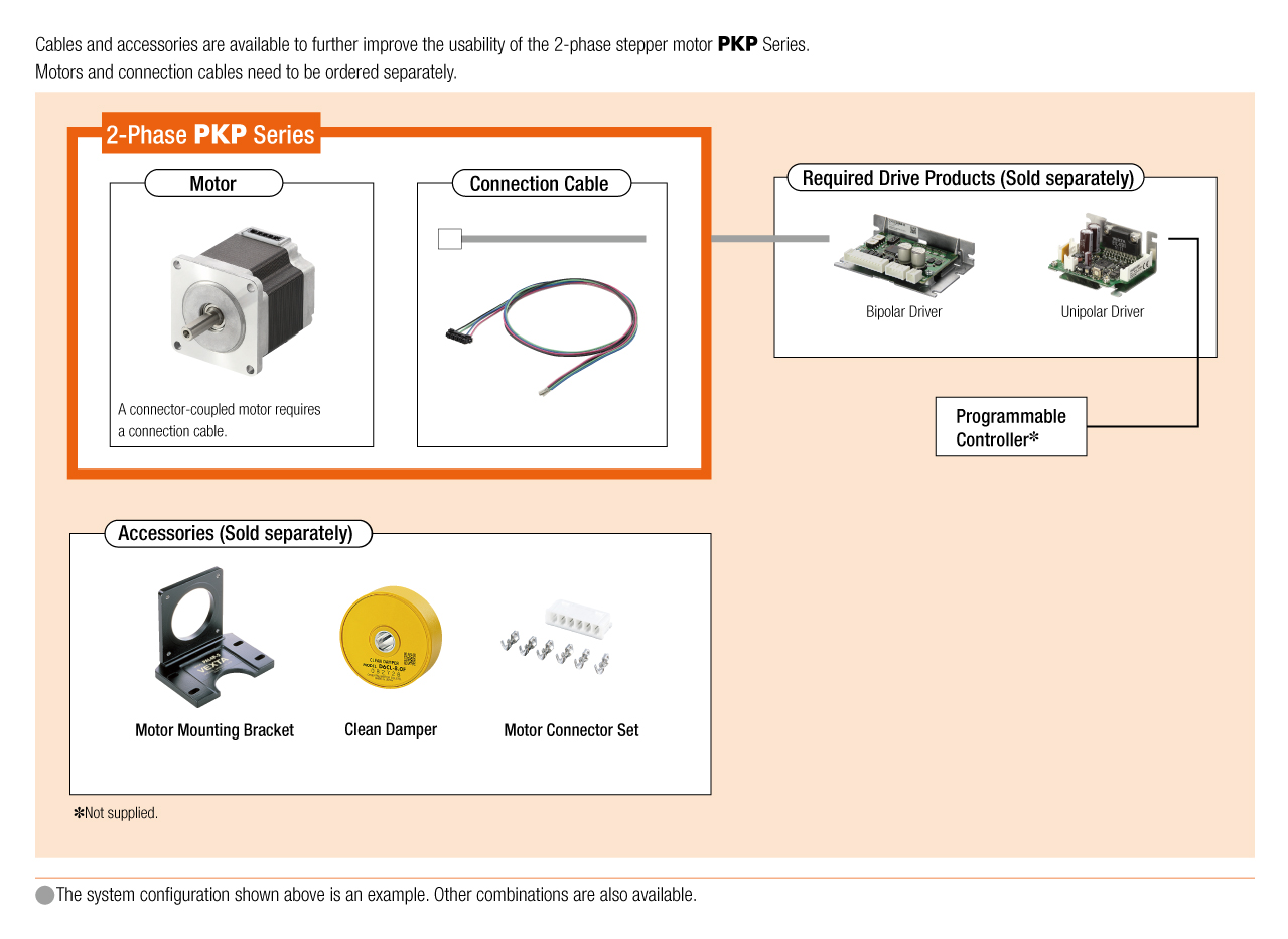
Kabel und Zubehör