Brushless Motors BLH Series
BLHM230KCM-200FR
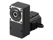
Motor


| Produktklassifikation | Produktname | Preis | Versand |
|---|---|---|---|
| Motor | BLHM230KCM-200FR | 534.00 € | Eingestelltes Produkt (Produktionsende 31.3.2026) |
Inklusive
- Motor: Varistor
Gearhead: Mounting Screws, Parallel Key, Safety Cover (with Screws)
Spezifikationen
Abmessungen
Daten-Download
Weitere Spezifikationen
General Specifications
| Item | Motor | Driver | |
|---|---|---|---|
| Insulation Resistance | 100 MΩ or more when a 500 VDC megger is applied between the windings and the case after continuous operation under normal ambient temperature and humidity. |
After continuous operation at normal ambient temperature and humidity, the value measured with a 500 VDC megger between the power supply input and the heat sink is min. 100 MΩ. |
|
| Dielectric Strength | No abnormality is observed even with an application of 1.5 kVAC at 50 Hz between the coils and the case for 1 minute after continuous operation at normal ambient temperature and humidity. |
After continuous operation at normal ambient temperature and humidity, the value measured with a 500 VDC megger between the power supply input and the heat sink is min. 100 MΩ. (Except for RS-485 communication type) |
|
| Temperature Rise | After continuous operation at normal ambient temperature and humidity, the measured value using the thermocouple method is 50 °Cmax. for the temperature rise of the coils and 40°C*1 max. for the temperature rise on the case surface. |
After continuous operation at normal ambient temperature and humidity, the measurement value of the temperature rise of the heat sink is 50 °C max. using the thermocouple method. |
|
| Operating Environment | Ambient Temperature | 0∼+50°C (Non-freezing) | |
| Ambient Humidity | 85 % max. (Non-condensing) | ||
| Altitude | Up to 1000 m above sea level | ||
| Atmosphere | No corrosive gases or dust Should not be exposed to water or oil. Cannot be used in a radioactive area, magnetic field, vacuum, or other special environments. |
||
| Vibration | Must not be subjected to continuous vibration or excessive shock. Conforms to JIS C 60068-2-6, "Sine-wave vibration test method." Frequency Range: 10~55 Hz, Half Amplitude: 0.15 mm Sweep direction: 3 directions (X, Y, Z) Number of sweeps: 20 |
||
| Storage Condition*2 | Ambient Temperature | -25~+70°C (Non-freezing) Electromagnetic Brake Motor: -20~+70°C (Non-freezing) |
-25~+70°C (Non-freezing) |
| Ambient Humidity | 85 % max. (Non-condensing) | ||
| Altitude | Up to 3000 m above sea level | ||
| Atmosphere | No corrosive gases or dust Should not be exposed to water or oil. Cannot be used in a radioactive area, magnetic field, vacuum, or other special environments. |
||
| Thermal Class | UL/CSA Standards: 105 (A), EN Standards: 120 (E) | − | |
| Degree of Protection | Connector Type/Lead Wire Type IP40 Cable Type, Electromagnetic Brake Motor: IP65 excluding the connector section and the round shaft type mounting surface) |
IP00 | |
- *1
- Attach round shaft types to a heat sink (Material: aluminum) of one of the following sizes to maintain a motor case surface temperature of 90 °C max. (Except BLHM015.)
Heat Sink Size
| Product Name | Size (mm) | Thickness (mm) |
|---|---|---|
| BLM015, BLM030, BLM230, BLHM230 | 115x115 | 5 |
| BLM250, BLM 450, BLHM450 | 135x135 | |
| BLHM5100 | 200x200 |
- *2
- The value for storage condition applies to short periods such as the period during transport.
Note
- Do not measure insulation resistance or perform a dielectric strength test the motor and driver are connected.
Permissible Radial Load and Permissible Axial Load
Parallel Shaft Gearhead
| Output | Gear Ratio | Permissible Radial Load |
Permissible Axial Load N |
|
|---|---|---|---|---|
|
10 mm From Shaft End N |
20 mm From Shaft End N |
|||
| 15 W | 5, 10, 15, 20 30, 50, 100 |
50 | − | 30 |
| 30 W | 5 | 100 | 150 | 40 |
| 10, 15, 20 | 150 | 200 | ||
| 30, 50, 100, 200 | 200 | 300 | ||
| 50 W | 5 | 200 | 250 | 100 |
| 10, 15, 20 | 300 | 350 | ||
| 30, 50, 100, 200 | 450 | 550 | ||
| 100 W | 5 | 300 | 400 | 150 |
| 10, 15, 20 | 400 | 500 | ||
| 30, 50, 100, 200 | 500 | 650 | ||
CS Geared Motor
| Output | Gear Ratio | Permissible Radial Load |
Permissible Axial Load N |
|
|---|---|---|---|---|
|
10 mm From the End of the Output Shaft N |
20 mm From the End of the Output Shaft N |
|||
| □42mm-15 W □42mm-30 W |
5 | 50 | - | 40 |
| 10, 15, 20 | 80 | - | ||
| □60mm-30 W □60mm-50 W |
5 | 150 | 190 | 70 |
| 10, 15, 20 | 200 | 260 | ||

Hollow Shaft Flat Gearhead
| Output | Gear Ratio | Permissible Radial Load |
Permissible Axial Load N |
|
|---|---|---|---|---|
|
10 mm From the Gearhead Mounting Surface N |
20 mm From the Gearhead Mounting Surface N |
|||
| 30 W | 5, 10 | 450 | 370 | 200 |
| 15, 20, 30, 50, 100, 200 | 500 | 400 | ||
| 50 W | 5, 10 | 800 | 660 | 400 |
| 15, 20, 30, 50, 100, 200 | 1200 | 1000 | ||
| 100 W | 5, 10 | 900 | 770 | 500 |
| 15, 20 | 1300 | 1110 | ||
| 30, 50, 100, 200 | 1500 | 1280 | ||
Round Shaft Type
| Output | Permissible Radial Load | Permissible Axial Load N |
|
|---|---|---|---|
|
10 mm From Shaft End N |
20 mm From Shaft End N |
||
| □42mm-15 W □42mm-30 W |
50 | − | 5 |
| □60mm-30 W □60mm-50 W |
70 | 100 | 15 (10) * |
| □80 mm-50 W | 120 | 140 | 20 |
| □90 mm-100 W | 160 | 170 | 25 |
- *The values in parentheses ( ) are for electromagnetic brake motor.
Permissible Radial Load Calculation
The formula for calculating the permissible radial load varies depending on the mechanism.
When One Side of the Load Shaft is Not Supported by the Bearing Unit
This is the mechanism in which the radial load is in the most severe condition. A stepped type load shaft is recommended.
| Product Name | Permissible Radial load W [N] |
|---|---|
| GFS2G□FR |
\(\begin{align} \mathrm{W} [\mathrm{N}] = \frac{36}{36 + \mathrm{Lp}} \times \mathrm{F}_0 [\mathrm{N}] \end{align}\)
|
| GFS4G□FR |
\(\begin{align} \mathrm{W} [\mathrm{N}] = \frac{40}{40 + \mathrm{Lp}} \times \mathrm{F}_0 [\mathrm{N}] \end{align}\)
|
| GFS5G□FR |
\(\begin{align} \mathrm{W} [\mathrm{N}] = \frac{50}{50 + \mathrm{Lp}} \times \mathrm{F}_0 [\mathrm{N}] \end{align}\)
|
When Supporting One Side of the Load Shaft with the Bearing Unit
| Product Name | Permissible Radial Load W [N] |
|---|---|
| GFS2G□FR GFS2G□FR GFS2G□FR |
\(\begin{align} \mathrm{W} [\mathrm{N}] = \frac{\mathrm{B}}{\mathrm{B} - \mathrm{Lp}} \times \mathrm{F}_0 [\mathrm{N}] \end{align}\)
|
| Product Name | Gear Ratio | F0[N] |
|---|---|---|
| GFS2G□FR | 5, 10 | 570 |
| 15~200 | 630 | |
| GFS2G□FR | 5, 10 | 1000 |
| 15~200 | 1500 | |
| GFS2G□FR | 5, 10 | 1080 |
| 15, 20 | 1550 | |
| 30 ~ 200 | 1800 |
Electromagnetic Brake Specifications
| Product Name | BLHM230 | BLHM450 | BLHM5100 |
|---|---|---|---|
| Type | Power Off Activated Type (for holding) | ||
| Power Supply Voltage | 24 VDC±10 % | ||
| Power Supply Current [A] | 0.084 | 0.31 | 0.31 |
| Brake Activation Time [ms] | 100 | ||
| Brake Release Time [ms] | 100 | ||
| Time Rating | Continuous | ||
Connecting the Electromagnetic Brake
Note
- When using the electromagnetic brake to hold a load, please first ensure the motor has stopped.
Operating the brake while it is rotating may damage the product.
Standards
Regulations and Standards Materials
Documents about compliance with regulations and standards can be downloaded from the "Data Download" tab on the product details page.
(The types of files available for download vary by product.)
Explanations of the Global Laws, Regulations and Standards can be found here.
Information about our compliance with safety standards for each of our product models can be found here.
Hazardous Substances
The product does not contain any substances (10 substances) exceeding the regulation values of the RoHS Directive (2011/65/EU, 2015/863/EU).
For more information about compliance with regulations on chemical substances in Oriental Motor's Products, click here.
Kabel und Zubehör