Induction Motors KII Series (New standard)
5IK40KJC-5L20B
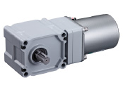
Motor
Dieses Produkt ist derzeit nicht mehr zum Verkauf verfügbar.
| Produktklassifikation | Produktname | Preis | Versand |
|---|---|---|---|
| Motor | 5IK40KJC-5L20B | - | Eingestelltes Produkt (Produktionsende 31.3.2024) |
Inklusive
- Capacitor, Capacitor Cap, Mounting Screws, Parallel Key (Iron), Operating Manual
Spezifikationen
Daten-Download
Weitere Spezifikationen
General Specifications
| Item | Specifications |
|---|---|
| Insulation Resistance | 100 MΩ or more when a 500 VDC megger is applied between the windings and the case after continuous operation under normal ambient temperature and humidity. |
| Dielectric Strength | No abnormality is observed when 1.5 kVAC at 50 Hz or 60 Hz applied between the coils and case for 1 minute after continuous operation under normal ambient temperature and humidity. |
| Temperature Rise | Winding temperature rise is 80 °C max. measured by the resistance change method after continuous operation with no load under normal ambient temperature and humidity. |
| Thermal Class | 130 (B) |
| Overheat Protective Device | Built-in thermal protector (automatic return type), Open: 130 ± 5 °C, Return: 85 ± 20 °C |
| Operating Ambient Temperature | 0~+40°C (Non-freezing) |
| Operating Ambient Humidity | 85 % max. (Non-condensing) |
| Degree of Protection | IP20 |
Permissible Radial Load and Permissible Axial Load of Gearhead
| Gear Ratio | 10 | 15 | 20 | 30 | 50 | 100 | 200 | ||
|---|---|---|---|---|---|---|---|---|---|
| Permissible Radial Load [N] *1 | Hollow Shaft*2 | 10 mm From Mounting Surface | 415 | 554 | 692 | 923 | 1112 | 1196 | 1291 |
| 20 mm From Mounting Surface | 363 | 484 | 605 | 806 | 971 | 1045 | 1127 | ||
| Solid Shaft | 10 mm From the End of the Output Shaft | 378 | 504 | 630 | 840 | 1011 | 1089 | 1174 | |
| 20 mm From the End of the Output Shaft | 481 | 641 | 802 | 1069 | 1287 | 1385 | 1495 | ||
| Permissible Axial Load [N] | 108 | 147 | 186 | 245 | 294 | 324 | 343 | ||
- *1
- The load position is shown below.
- *2
- For calculations of the radial load from every distance for the hollow shaft type, refer to "Permissible radial load calculation for hollow shaft type" below.
Calculating the Permissible Radial Load for Hollow Shaft Type
The formula for calculating the permissible radial load varies depending on the mechanism.
Systemkonfiguration

Kabel und Zubehör
close