Stepper Motors PKP Series/PK Series (2-Phase)
PK266JA
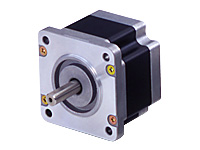
Motor
| Produktklassifikation | Produktname | Preis | Versand |
|---|---|---|---|
| Motor | PK266JA | 101.00 € | Up to 30 pcs Estimated Ship 4weeks |
Inklusive
- Motor: None
Spezifikationen
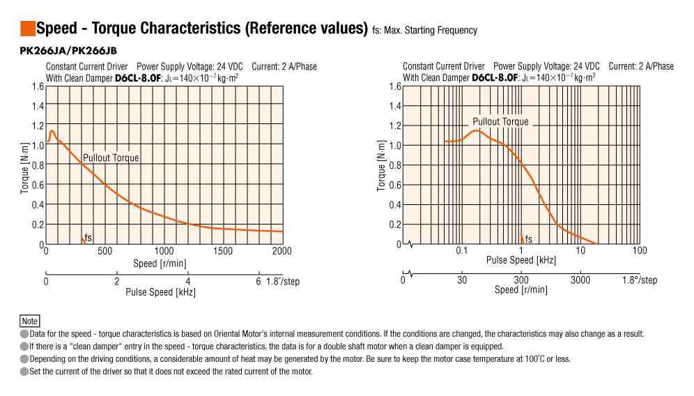
Kennlinien
Abmessungen
Daten-Download
Weitere Spezifikationen
General Specifications
| Specifications | Motor | |
|---|---|---|
| Thermal Class | 130 (B) [Standard Type With Terminal Box: UL/CSA Standards is approved at 105(A).] | |
| Insulation Resistance | The measured value is 100 MΩ min. when a 500 VDC megger is applied between the windings and the case under normal ambient temperature and humidity. | |
| Dielectric Strength | Under normal ambient temperature and humidity, no abnormalities were observed even if 1.0 kV at 50 Hz or 60 Hz is applied between the windings and the case of the motor for 1 minute. (0.5 kV for frame sizes of 42 mm max., and 1.5 kV for standard type with terminal box PK29□D) |
|
| Operating Environment (In operation) | Ambient Temperature | -10~+50 °C (non-freezing) |
| Ambient Humidity | 85 % max. (Non-Condensing) | |
| Atmosphere | No corrosive gases or dust Should not be exposed to water or oil. (Standard Type with Terminal Box: No corrosive gases. Should not be exposed to oil.) |
|
| Temperature Rise |
|
|
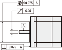
| Stop Position Accuracy*1 | ±3 arcmin (±0.05˚), PK26□J, PK26□JD: ±2 arcmin (±0.034˚) | |
| Shaft Runout | 0.05 T.I.R. (mm)*4 | |
| Radial Play*2 | 0.025 mm Max. (Load 5 N) | |
| Axial Play*3 | 0.075 mm max. (Load 10 N) [Load 1 N for PK21□, Load 2.5 N for PK22□] | |
| Concentricity of Installation Pilot to the Shaft | 0.075 T.I.R. (mm)*4 | |
| Perpendicularity of Mounting Surface to the Shaft | 0.075 T.I.R. (mm)*4 | |
- *1
- This value is for full step under no load. (The value changes with the size of the load.)
- *2
- Radial Play: Displacement in shaft position in the vertical direction when a 5 N load is applied perpendicular to the tip of the motor shaft.
- *3
- Axial Play: Displacement in shaft position in the axial direction when a 10 N (1 N for PK21□, 2.5 N for PK22□) load is applied to the motor shaft in the axial direction.
- *4
- T.I.R. (Total Indicator Reading): The total dial gauge reading when the measurement section is rotated 1 revolution centered on the reference axis center.
Note
- Disconnect the motor and driver when measuring insulation resistance, or conducting a dielectric strength test.
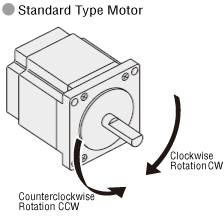
Rotation Direction
This indicates the rotation direction when viewed from the output shaft side.
The rotation direction of the gearhead output shaft relative to the standard type motor output shaft varies depending on the gear type and gear ratio. Please check the following table.
| Type | Gear Ratio | Rotation Direction as Viewed From the Motor Output Shaft Side |
|---|---|---|
| TS Geared Type | 3.6, 7.2, 10 | Same direction |
| 20, 30 | Opposite direction | |
| TH Geared Type Frame size 28 mm |
7.2, 10 | Opposite direction |
| 20, 30 | Same direction | |
| TH Geared Type Frame size 42 mm, 60 mm, 90 mm |
3.6, 7.2, 10 | Same direction |
| 20, 30 | Opposite direction | |
| SH Geared Type Frame size 28 mm |
7.2, 36 | Same direction |
| 9, 10, 18 | Opposite direction | |
| SH Geared Type Frame size 42 mm, 60 mm |
3.6, 7.2, 9, 10 | Same direction |
| 18, 36 | Opposite direction | |
| SH Geared Type Frame size 90 mm |
3.6, 7.2, 9, 10, 18 | Same direction |
| 36 | Opposite direction | |
| CS Geared Type | 5, 10, 15, 20 | Same direction |
|
FC Geared Type PS Geared Type PN Geared Type HPG Geared Type |
Overall gear ratio | Same direction |
| Harmonic Geared Type | 50, 100 | Opposite direction |
Permissible Radial Load and Permissible Axial Load
Unit: N
| Type | Motor Frame Size | Motor Product Name | Gear Ratio | Permissible Radial Load | Permissible Axial Load | ||||
|---|---|---|---|---|---|---|---|---|---|
| Distance From Shaft End [mm] | |||||||||
| 0 | 5 | 10 | 15 | 20 | |||||
| High-Resolution Type / High-Resolution Type With Encoder / High-Resolution Type With electromagnetic brake |
42 mm | PKP243, PKP244, PKP544, PKP546 | - | 20 | 25 | 34 | 52 | - | 10 |
| 56.4 mm | PKP264, PKP266, PKP268 | 54 | 67 | 89 | 130 | - | 20 | ||
| 60 mm | PKP564, PKP566, PKP569 | 90 | 100 | 130 | 180 | 270 | 20 | ||
| Standard Type / Standard Type With Encoder / Standard Type With electromagnetic brake |
20 mm | PKP213, PKP214 | 12 | 15 | - | - | - | 3 | |
| 28 mm | PKP223, PKP224, PKP225, PKP523, PKP525 |
25 | 34 | 52 | - | - | 5 | ||
| 35 mm | PKP233, PKP235 | 20 | 25 | 34 | 52 | - | 10 | ||
| 42 mm | PKP243, PKP244, PKP245, PKP246, PKP544, PKP546 |
20 | 25 | 34 | 52 | - | 10 | ||
| 50 mm | PK256, PK258 | 54 | 67 | 89 | 130 | - | 20 | ||
| 56.4 mm | PKP264, PKP266, PKP268 | 61 | 73 | 90 | 110 | 160 | 20 | ||
| 60 mm | PKP564, PKP566, PKP569 | 63 | 75 | 95 | 130 | 190 | 20 | ||
| PKP262 | 20 | 25 | 34 | - | - | 5 | |||
| PK264J, PK266J, PK267J, PK269J | 50 | 60 | 75 | 100 | 150 | 20 | |||
| 85 mm | PK296, PK299, PK2913, PKP296, PKP299, PKP2913 |
260 | 290 | 340 | 390 | 480 | 60 | ||
| SH Geared Type | 28 mm | PKP223 | 7.2, 9, 10, 18, 36 | 15 | 17 | 20 | 23 | - | 10 |
| 42 mm | PKP243 | 3.6, 7.2, 9, 10, 18, 36 | 10 | 15 | 20 | 30 | - | 15 | |
| 60 mm | PKP264 | 3.6, 7.2, 9, 10 | 30 | 40 | 50 | 60 | 70 | 30 | |
| 18, 36 | 80 | 100 | 120 | 140 | 160 | ||||
| 90 mm | PK296 | 3.6, 7.2, 9, 10, 18, 36 | 220 | 250 | 300 | 350 | 400 | 100 | |
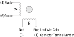
Inner Wiring Diagram of Motor
-
Unipolar (6 lead wires)
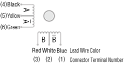
-
Bipolar (4 lead wires)
Standard Type with Terminal Box
PK26□AT
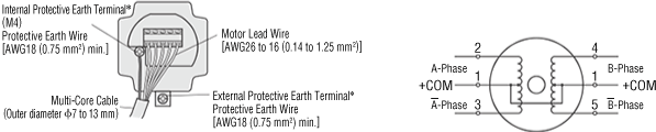
PK26□DAT, PK26□D1T
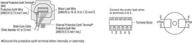
- A number indicating the length of the motor case is placed in □ in the product name.
PK29□EAT
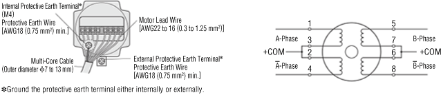
PK29□DT
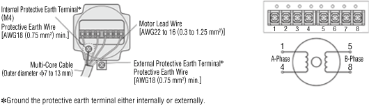
- A number indicating the length of the motor case is placed in □ in the product name.
Standards
Hazardous Substances
The product does not contain any substances (10 substances) exceeding the regulation values of the RoHS Directive (2011/65/EU, 2015/863/EU).
For more information about compliance with regulations on chemical substances in Oriental Motor's Products, click here.
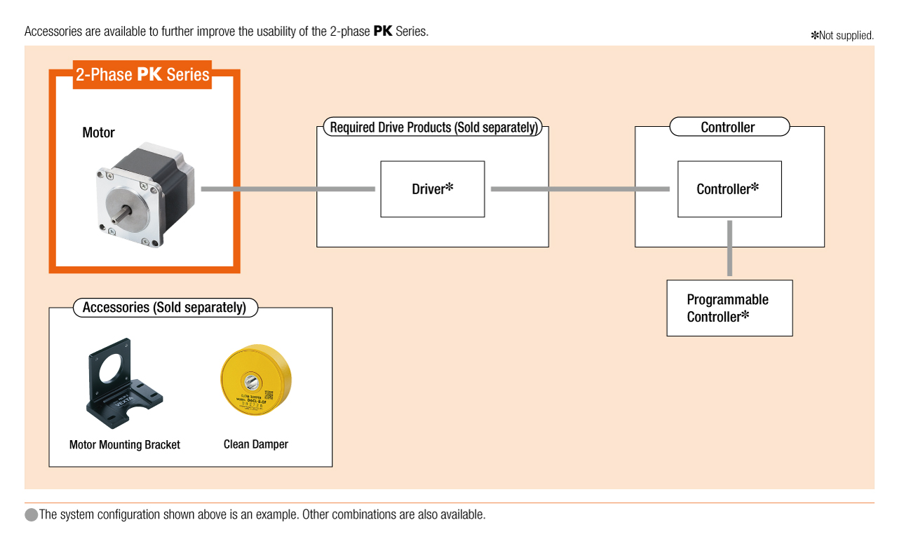
Systemkonfiguration
Kabel und Zubehör
close
close
close