Motor Hands MHB Series
MHB4Y-C
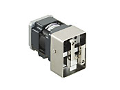
Actuator/Control Circuit
| Product Classification | Product Name | List Price | Shipping Date |
|---|---|---|---|
| Actuator / Control Circuit | MHB4Y-C | - | Discontinued Product (1.4.2015 discontinued) |
Included
- Actuator, Control Circuit, Connector, Connector Cover, Operating Manual
Specifications
Other Specifications
Maximum Load Moment
The maximum load moment based on the tip of the finger. Take into consideration the mass of the load and clamping claw, the impact load during gripping, etc., and use under the maximum load moment.
[Clamping claw length] L = 80 mm or less when using clamping claw as shown in the above figure with maximum gripping force
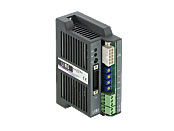
Circuit Specifications
| Product Name | MHCB10 | |
|---|---|---|
| Power Supply Input | Voltage | 24 VDC±10 % |
| Current | 0.3 A max. | |
| Input Signals | Input Mode | Photocoupler input, Input resistance 4.7 kΩ |
| OPEN | Input when opening a finger | |
| CLOSE | Input when closing the finger | |
| EXT/INT.VR | Select the gripping force setting method | |
| Output Signals | Output Mode | 24 VDC Photocoupler and Open-Collector Output 24 VDC 10 mA max. |
| GRIP | Outputs when the set gripping force is reached. | |
| ALARM | Outputs when an abnormality occurs. | |
| Protective Function | Overheat protection, phase interruption protection | |
| Indicator (LED) | POWER indicator, ALARM indicator | |
| Cooling Method | Natural Cooling Method | |
| Mass | 0.31 kg | |
Sensor Specifications
(MHB4Z and MHB4Y only)
| Product Name | GXL-8H (Made by Sunx) |
|---|---|
| Power Supply Voltage | 12~24 VDC±10 % Ripple (p-p) 10 % max. |
| Current consumption | 15 mA max. |
| Control output | NPN open-collector output 30 VDC 100 mA max. Residual voltage 1 VDC or less (at load current of 100 mA) |
| Display LED | Detection Display (Red) |
| Logic | Normally open |
General Specifications
Values are after rated operation at normal ambient temperature and humidity.
| Item | Motor | Controller Part |
|---|---|---|
| Insulation Resistance |
100 MΩ or more when a 500 VDC megger is applied between the following places.
|
100 MΩ or more when a 500 VDC megger is applied between the following places.
|
| Dielectric Strength |
No abnormalities observed with application for 1 minute at the following points:
|
No abnormalities observed with application for 1 minute at the following points:
|
| Operating Ambient Temperature | 0~+40 °C (non-freezing) | |
| Operating Ambient Humidity | 85 % max. (Non-condensing) | |
Note
- Do not perform insulation resistance measurements or dielectric voltage tests while the motor and speed controller are connected.
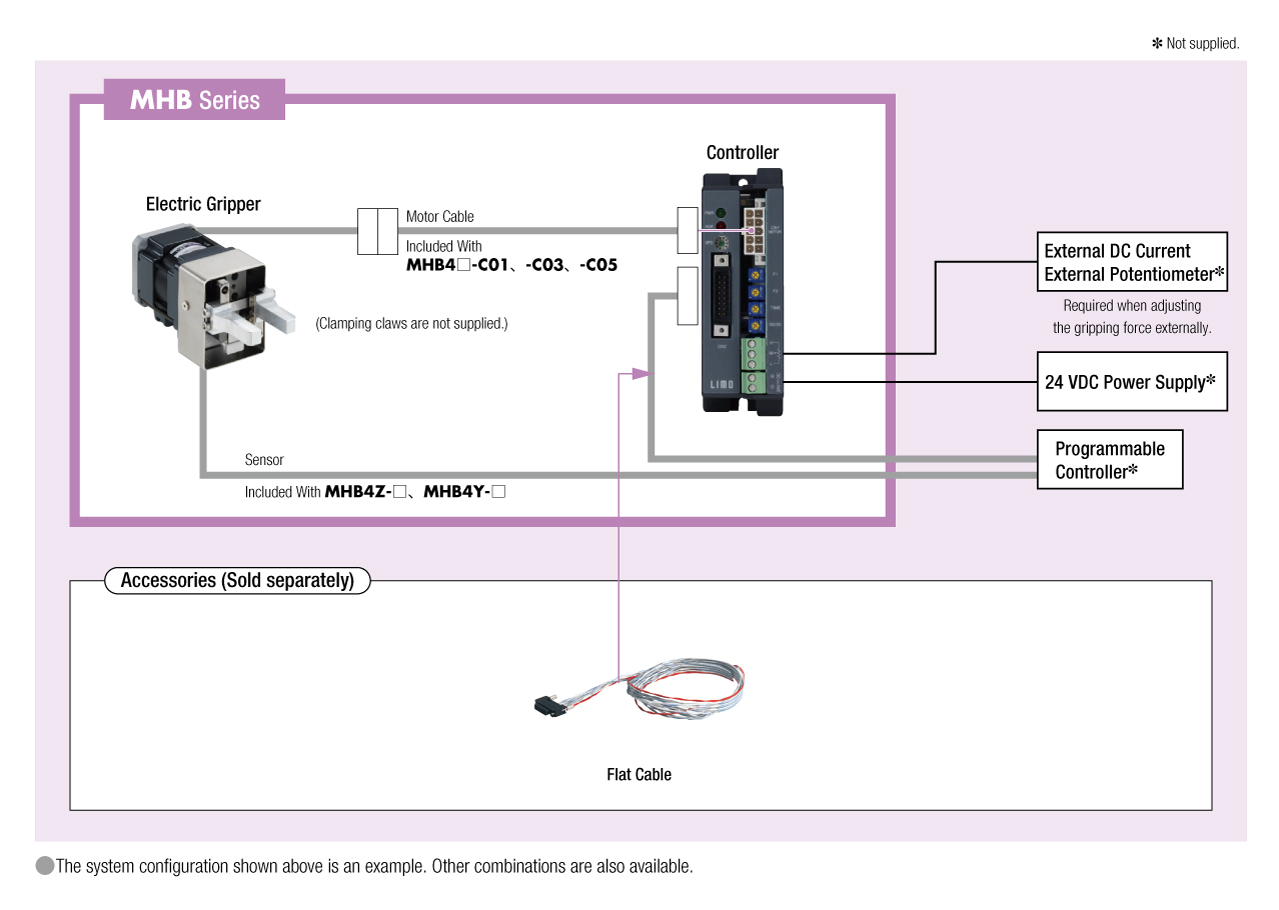
System Configuration