Rack-and-Pinion System LAS Series
LAS4B500AS-4
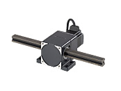
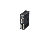
Rack and Pinion Motor/Control Circuit
This product is currently no longer available for sale.
| Product Classification | Product Name | List Price | Shipping Date |
|---|---|---|---|
| Rack and Pinion Motor / Control Circuit | LAS4B500AS-4 | - | Discontinued Product (31.3.2020 discontinued) |
Included
- Rack and Pinion Motor, Control Circuit, Connector for I/O Signal, Operating Manual
Specifications
Other Specifications
General Specifications
Values are after rated operation at normal ambient temperature and humidity.
| Item | Motor | Driver |
|---|---|---|
| Insulation Class | Class B (130 °C) [Recognized as Class A (105 °C) by UL/CSA Standards.] | - |
| Insulation Resistance |
100 MΩ or more when a 500 VDC megger is applied between the following places:
|
100 MΩ or more when a 500 VDC megger is applied between the following places:
|
| Dielectric Strength |
Sufficient to withstand the following for 1 minute:
|
Sufficient to withstand the following for 1 minute:
|
| Operating Ambient Temperature | 0~+50 °C (non-freezing) | |
| Operating Ambient Humidity | 85 % max. (Non-condensing) | |
- Do not measure insulation resistance or perform the dielectric strength test while the rack and pinion motor and the driver are connected.
Circuit Specifications
| Product Name | LSD20A-W | LSD20B-W | LSD20A-S | LSD20B-S | |
|---|---|---|---|---|---|
| Power Supply Input | Voltage | Single-phase 100/115 VAC, Single-phase 200/230 VAC -15~+10 % | Three-phase 200-230 VAC -15~+10 %. | ||
| Frequency | 50/60 Hz | ||||
| Current | 3.2 A (100 V) 3.7 A (200 V) |
4.1 A (100 V) 4.5 A (200 V) |
2.0 A | 2.4 A | |
| Maximum Input Pulse Frequency | 250 kHz (at 50 % duty) | ||||
| Input Signals | Input Mode | Photocoupler Input, Input Resistance: 220 Ω, Input current 7~20 mA | |||
|
DIR.-A direction operation command pulse signal (pulse input when 1-pulse input mode) Pulse width 2 μs min., rise/fall time 2 μs max. (Negative logic pulse input) |
||||
|
DIR.-B direction operation command pulse signal (operation direction switch input when 1-pulse input mode) Pulse width 2 μs min., rise/fall time 2 μs max. (Negative logic pulse input) |
||||
|
Input when protective function is activated to clear the alarm status. | ||||
|
When the photocoupler is ON, output current to the rack and pinion motor is turned OFF. When the photocoupler is OFF, the current is supplied to the rack and pinion motor. |
||||
|
When the photocoupler ON, the resolution is 10 times the resolution at power on. When the photocoupler is OFF, the resolution is the resolution at power on. |
||||
| Output Signals | Output Mode | Photocoupler and Open-collector output External use condition 30 VDC max, 15 mA max (Positioning completion, Alarm) Transistor and Open-collector output External use condition 30 VDC max, 15 mA max (Timing, Feedback pulse phase A and B) Line driver output 26C31 equivalent (Timing, Feedback pulse phase A and B) |
|||
|
1-pulse outputs each time the rack moves the value shown in Table 1. (Photocoupler: ON) Available in 500 Hz max. in maximum speed input pulse frequency. |
||||
|
Outputs when the protective function is activated. (Photocoupler: OFF) Alarm outputs (Blinking red LED), while at the same time, the rack and pinion motor comes to a coasting stop. |
||||
|
Outputs on positioning completion. (Photocoupler: ON) Output is within ±0.05 mm of the command position at a pulse speed of 500 Hz max. |
||||
|
Outputs at the resolution when the driver is powered on. The phase difference between phase A and phase B is 90˚ in electrical angle. There is a time lag of up to 1 ms relative to the actual motion of the rack and pinion motor. Use to confirm the stop position. |
||||
| Protective Function | Overheat protection, overload protection, overvoltage protection, speed error protection, overcurrent protection, overspeed protection EEPROM data error, sensor error, system error |
||||
| Mass | 0.8 kg | ||||
Table 1
TIM. Output Signal Travel Amount
| Product Name | LAS2□90 | LAS2□500 | LAS4□40 | LAS4□500 |
|---|---|---|---|---|
| Travel amount [mm] | 37.364 × 10⁻³ | 199.948× 10⁻³ | 14.835 × 10⁻³ | 200.176 × 10⁻³ |
- Either F or B indicating the rack moving direction is specified where the box □ is located in the product name.
Maximum Radial Load
| Stroke mm |
Maximum Radial Load N |
|||
|---|---|---|---|---|
| LAS2□90 | LAS2□500 | LAS4□40 | LAS4□500 | |
| 100 | 25 | 25* | 120 | 60* |
| 200 | 20 | 20* | 90 | 40* |
| 300 | 10 | 10* | 70 | 30* |
| 400 | 10 | 10* | 60 | 25* |
| 500 | 7 | 7* | 50 | 20* |
| 600 | - | - | 40 | 15* |
| 700 | - | - | 40 | 10* |
| 800 | - | - | 25 | 7* |
| 900 | - | 20 | - | |
| 1000 | - | 15 | - | |
- Either F or B indicating the rack moving direction is specified where the box □ is located in the product name.
- *Keep the operating speeds up to 90 mm/s, do not apply the radial load for use over 90 mm/s.
Install an external guide when using.
Rack Permissible Rotational Torque (Moment)
The rotational torque applied to the rack should be less than the value shown in the table below.
| Rack and Pinion Motor Product Name | Rack Permissible Rotational Torque (Moment) |
|---|---|
| LAS2B(F) | 0.3 N·m max. |
| LAS4B (F) | 0.5 N·m max. |
- Be sure to keep rotational torque below the permissible value. If too much rotational torque is applied, the abrasion of rack bushings will be sped up.
Repetitive Positioning Accuracy (Reference value)
The graph on the figure below shows the actual measurement value at maximum transportable mass. Varies depending on the load, driving conditions, and mounting direction.
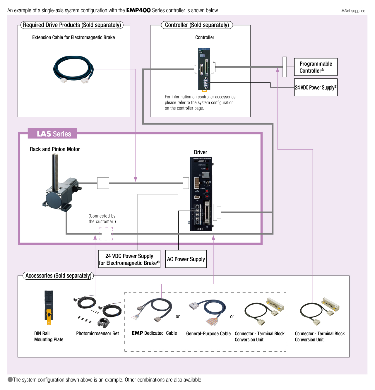
System Configuration
Cables and Accessories
close