Stepper Motors CSKII Series
CSK543AP-T3.6
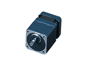
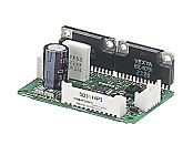
Geared Motor/Control Circuit
This product is currently no longer available for sale.
| Product Classification | Product Name | List Price | Shipping Date |
|---|---|---|---|
| Motor / Control Circuit | CSK543AP-T3.6 | - | Discontinued Product (31.3.2019 discontinued) |
Included
- Motor, Control Circuit, Connector Housing, Contact, Operating Manual
Specifications
Other Specifications
Circuit Specifications
| Input Signals | Input Mode | Photocoupler input, input resistance 220 Ω, input current 10~20 mA, photocoupler "ON": +4.5~5 V, photocoupler "OFF": 0~+1 V (terminal voltage) |
|---|---|---|
| CW Pulse Signal | CCW direction movement command pulse signal Pulse width 5 μs min., rise/fall time 2 μs max., pulse duty 50 % max. When the pulse input is turned from "ON" to "OFF," the motor rotates 1 step. Maximum response frequency 100 kHz (at 50 % pulse duty) Negative logic pulse input |
|
| CCW Pulse Signal | CCW direction movement command pulse signal Pulse width 5 μs min., rise/fall time 2 μs max., pulse duty 50 % max. When the pulse input is turned from "ON" to "OFF," the motor rotates 1 step. Maximum response frequency 100 kHz (at 50 % pulse duty) Negative logic pulse input |
|
| Step Angle Select Input Signal | Full step when the photocoupler is "OFF" Half step when photocoupler is "ON” |
|
| All Windings Off Signal | When the photocoupler is "ON," the output current to the motor is turned "OFF," and the motor shaft can be turned by external force. When the photocoupler is "OFF," output current to the motor is turned "ON." |
|
| Current Cutback Release signal | When the photocoupler is "ON," the automatic current cutback function is canceled at motor standstill. When the photocoupler is "OFF," the automatic current cutback function will be activated at motor standstill (after approx. 100 ms). |
|
| Output Signals | Output Mode | Photocoupler and open-collector output External Use Conditions: 24 VDC max., 10 mA max. |
| Excitation Timing Signal | This signal is output when the excitation sequence is step "0." At Full Step: Output once every 10 pulses. At Half Step: Output once every 20 pulses. |
|
| Function | Automatic current cutback, step angle switching, all windings off, excitation timing | |
| Cooling Method | Natural cooling method | |
General Specifications
| Specifications | Motor | Driver | |
|---|---|---|---|
| Insulation Class | Class B (130 °C) [UL Standards is approved to Class A (105 °C)] | - | |
| Insulation Resistance | 100 MΩ or more when a 500 VDC megger is applied between the motor windings and the case under normal ambient temperature and humidity. | - | |
| Dielectric Strength |
Under normal ambient temperature and humidity, no abnormalities were observed even with 1.5 kV* at 50 Hz and 60 Hz applied between the windings and the case of the motor for 1 minute.
|
- | |
| Operating Environment (In operation) | Ambient Temperature | 0~+40 °C (Non-freezing) | 0~+40 °C (Non-freezing) |
| Ambient Humidity | 85 % max. (Non-condensing) | ||
| Atmosphere | No corrosive gases or dust. No exposure to water, oil or other liquids. | ||
| Temperature Rise | 5-phase excitation at rated current, winding temperature rise to 80 °C max. at standstill (resistance change method) | - | |
| Stop position accuracy*1 | ±3 arcmin (±0.05˚) CSK52□ ±5 arcmin (±0.084˚) CSK513P□±10 arcmin (±0.17˚) | - | |
| Shaft Runout | 0.05 T.I.R. (mm)*4 | - | |
| Radial Play*2 | 0.025 mm Max. (Load 5 N) | - | |
| Axial Play*3 | 0.075 mm Max. (Load 10 N) | - | |
| Concentricity of Installation Pilot to the Shaft | 0.075 T.I.R. (mm)*4 | - | |
| Perpendicularity of mounting surface to the shaft | 0.075 T.I.R. (mm)*4 | - | |
- *1
- This is the value at full step and no load (Varies depending on the size of the load).
- *2
- Radial Play: Displacement in shaft position in the radial direction when a 5 N load is applied perpendicular to the tip of the motor shaft.
- *3
- Axial Play: Displacement in shaft position in the axial direction when a 10 N load is applied to the motor shaft in the axial direction.
- *4
- T.I.R. (Total Indicator Reading): The total dial gauge reading when the measurement section is rotated 1 revolution centered on the reference axis center.
Note
- Do not measure insulation resistance or perform a dielectric strength test while the motor and driver are connected.
Permissible Radial Load and Permissible Axial Load
Unit: N
| Product Name | Gear Ratio | Permissible Radial Load | Permissible Axial Load | ||||
|---|---|---|---|---|---|---|---|
| Distance From Shaft End [mm] | |||||||
| 0 | 5 | 10 | 15 | 20 | |||
| CSK513P□P | - | 12 | 15 | - | - | - | Less than or equal to motor weight |
| CSK523□P CSK525□P |
25 | 34 | 52 | - | - | ||
| CSK543□P CSK544□P CSK545□P |
20 | 25 | 34 | 52 | - | ||
| CSK544P□P CSK546P□P |
20 | 25 | 34 | 52 | 480 | ||
| CSK564□P CSK566□P CSK569□P |
63 | 75 | 95 | 130 | 190 | ||
| CSK566H□P CSK569H□P |
63 | 75 | 95 | 130 | 190 | ||
| CSK596H□P CSK599H□P CSK5913H□P |
260 | 290 | 340 | 390 | 480 | ||
| CSK523□P-M■ | 7.2, 10, 20, 30 | 9.2 | 11.4 | 15 | 21.9 | - | 10 |
| CSK543□P-T■ | 3.6, 7.2, 9, 10, 20, 30 | 10 | 14 | 20 | 30 | - | 15 |
| CSK564□P-T■ | 3.6, 7.2, 9, 10, 20, 30 | 70 | 80 | 100 | 120 | 150 | 40 |
| CSK543□P-P■ | 25, 36, 50 | 109 | 127 | 150 | 184 | - | 50 |
| CSK545□P-P■ | 5,7.2,10 | 73 | 84 | 100 | 123 | - | 50 |
| CSK564□P-P■ | 25, 36, 50 | 330 | 360 | 400 | 450 | 520 | 100 |
| CSK566□P-P■ | 5 | 200 | 220 | 250 | 280 | 320 | |
| 7.2,10 | 250 | 270 | 300 | 340 | 390 | ||
| CSK544□P-N■ | 5,7.2,10 | 100 | 120 | 150 | 190 | - | |
| CSK564□P-N■ | 25, 36, 50 | 330 | 360 | 400 | 450 | 520 | |
| CSK566□P-N5 | 5 | 200 | 220 | 250 | 280 | 320 | |
| CSK566□P-N■ | 7.2,10 | 250 | 270 | 300 | 340 | 390 | |
| CSK523□P-H■ | 50, 100 | 140 | 160 | 200 | 240 | - | |
| CSK543□P-H■ | 180 | 220 | 270 | 360 | 510 | 220 | |
| CSK564□P-H■ | 320 | 370 | 440 | 550 | 720 | 450 | |
- Either A or B indicating the motor shaft type is specified where the box □ is located in the product name.
A number indicating the gear ratio is specified where the box ■ is located in the product name.
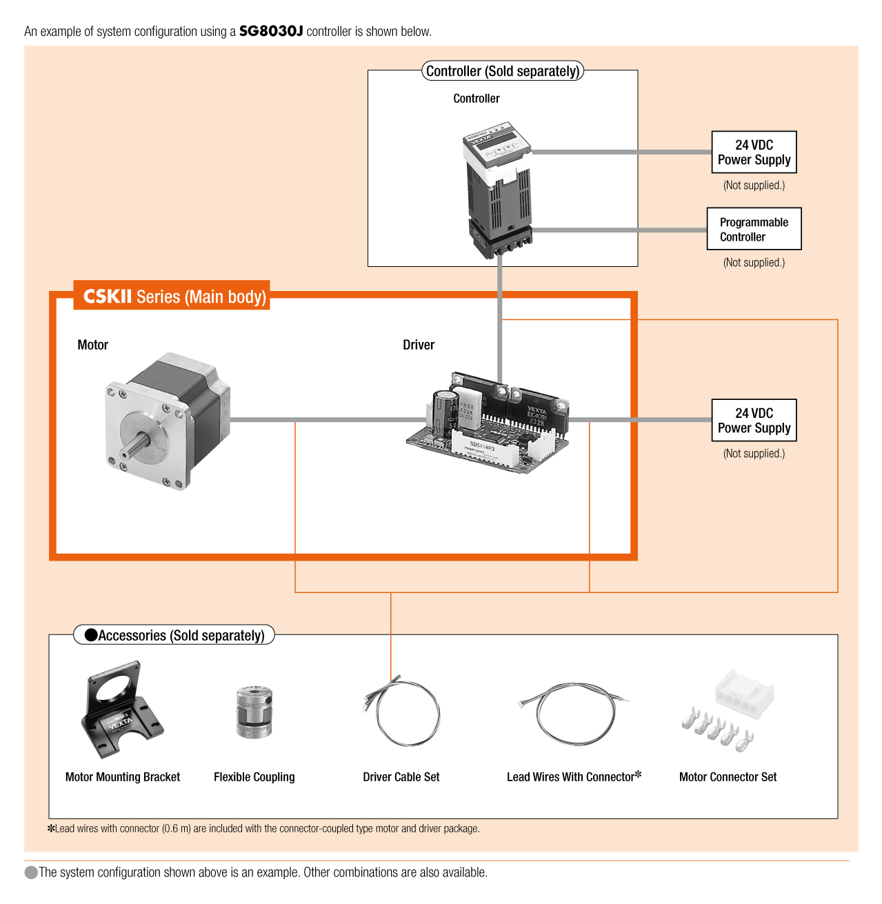
System Configuration
Cables and Accessories
close