Electromagnetic Brake Motors
5RK40A-CW2MBSE
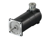
Motor
| Product Classification | Product Name | List Price | Shipping Date |
|---|---|---|---|
| Motor | 5RK40A-CW2MBSE | - | Discontinued Product (1.4.2015 discontinued) |
Included
- Motor, Capacitor, Capacitor Cap, Operating Manual
Specifications
Characteristics
Starting and Braking Characteristics (Reference values)
Dimensions
Capacitor
Data Download
Other Specifications
General Specifications
| Item | Specifications |
|---|---|
| Insulation Resistance | After rated operation at normal ambient temperature and humidity, the measurement between the coils and the case is 100 MΩ min. using a 500 VDC megger. |
| Dielectric Strength | After continuous rated operation at normal ambient temperature and humidity, no abnormalities were observed even with an application of 1.5 kV at 50 Hz or 60 Hz between the coils and the case for 1 minute. |
| Temperature Rise | After a gearhead or equivalent heat sink*is connected for rated operation at normal ambient temperature and humidity, the measurement value of the winding temperature rise is 70 °C max. using the resistance change method. |
| Thermal Class | 130 (B) |
| Overheat Protective Device |
Thermal protector operating temperature Open: 130 ±5 °C, Return: 90 ±15 °C (normally closed) |
| Operating Ambient Temperature | Single-phase 100 V, single-phase 200 V, three-phase 200 V: -10~+50 °C (Non-freezing) Other voltages: -10~+40 °C (Non-freezing) |
| Operating Ambient Humidity | 85 % max. (Non-condensing) |
| Degree of Protection | IP65 (excluding mounting surface of the round shaft type) |
- *Heat Sink Size (Material: Aluminum)
| Motor Type (Output power) | Size (mm) | Thickness (mm) |
|---|---|---|
| 6 W type | 115 × 115 | 5 |
| 15 W type | 125 × 125 | |
| 25 W type | 135 × 135 | |
| 40 W type | 165 × 165 |
Permissible Radial Load and Permissible Axial Load of Round Shaft Type
Permissible Radial Load
| Motor | Permissible Radial Load N | ||
|---|---|---|---|
| Frame Size □ (mm) | Output Shaft Diameter φ (mm) | From Shaft End 10 mm |
From Shaft End 20 mm |
| 42 | 5 | 40 | - |
| 60 | 6 | 50 | 110 |
| 70 | 6 | 40 | 60 |
| 80 | 8 | 90 | 140 |
| 90 | 10 | 140 | 200 |
| 12 | 240 | 270 | |
Permissible Axial Load
Avoid axial load as much as possible. If an axial load is unavoidable, keep it at half or less of the motor mass.
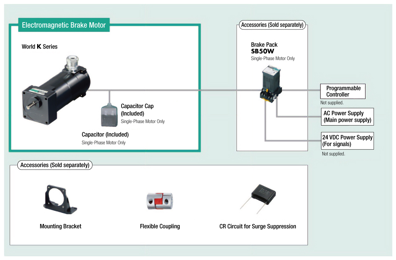
System Configuration
Related Products
Brake Pack
| Products | Features | |
|---|---|---|
SB50W Series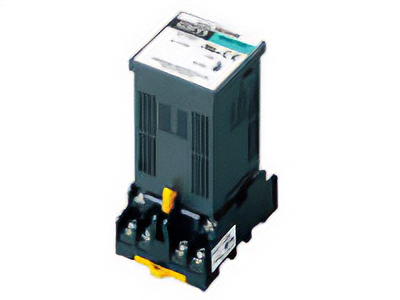
|
Features |
This is a brake pack that enables instantaneous stopping, bidirectional rotation, and brake control of the motor, all in 1 unit.
|