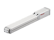
Electric Cylinder EZ-limo EZA Series
EZA4D021M-A
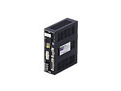
Actuator/Control Circuit
| Product Classification | Product Name | List Price | Shipping Date |
|---|---|---|---|
| Actuator / Control Circuit | EZA4D021M-A | - | Discontinued Product (1.4.2018 discontinued) |
Included
- Actuator, Control Circuit, Circuit Mounting Bracket, User I/O Connector, Sensor I/O Connector, Operating Manual
Specifications
Other Specifications
General Specifications (Motor)
Values are after rated operation at normal ambient temperature and humidity.
24 VDC
| Item | Specifications |
|---|---|
| Insulation Resistance |
100 MΩ or more when 500 VDC megger is applied between the following places.
|
| Dielectric Strength |
No abnormalities observed with application for 1 minute at the following points.
|
| Operating Ambient Temperature | 0~+40 °C (Non-freezing) |
| Operating Ambient Humidity | 85 % max. (Non-condensing) |
Note
- Do not measure insulation resistance or perform a dielectric strength test while the cylinder and controller are connected.
Single-Phase 100/115 VAC, Single-Phase 200/230 VAC
| Item | Specifications |
|---|---|
| Insulation Resistance |
100 MΩ or more when 500 VDC megger is applied between the following places.
|
| Dielectric Strength |
No abnormalities observed with application for 1 minute at the following points.
|
| Operating Ambient Temperature | 0~+40 °C (Non-freezing) |
| Operating Ambient Humidity | 85 % max. (Non-condensing) |
Note
- Do not measure insulation resistance or perform a dielectric strength test while the cylinder and controller are connected.
Circuit Specifications (Controller Mode)
Controller Mode
| Item | Controller Parts Name | ||||
|---|---|---|---|---|---|
| ESMC-K2 | ESMC-A2 | ESMC-C2 | |||
| Product Line | Stored data type | ||||
| Power Supply Input | Control Power Supply | 24 VDC±5 % 1.0 A [0.5 A only for controller (see +0.2 A with teaching pendant, +0.3 A with electromagnetic brake)]. | |||
| Main Power Supply | Voltage | 24 VDC±10 % | Single-phase 100-115 VAC −15~+10 % | Single-phase 200-230 VAC −15~+10 % | |
| Frequency | - | 50/60 Hz | |||
| Current | 4.0 A*1 | 6.0 A*1 | 3.5 A*1 | ||
| Positioning Data |
Setting Mode | Absolute mode (absolute-position specification), incremental mode (relative-position specification) | |||
| Setting Number | 63 points | ||||
| Setting Method | Setting by accessory teaching pendant (EZT1) or data setting software (EZED2) (Stored in EEPROM) | ||||
| Positioning*2 Control |
Method | Sequential positioning, Data-select positioning | |||
| Traveling Amount Setting Range | -83886.08~+83886.07 mm (in 0.01 mm units) | ||||
| Starting Speed Setting Range | 0.01~200.00 mm/s (in 0.01 mm/s units) | ||||
| Operating Speed Setting Range | 0.01~1500.00 mm/s (in 0.01 mm/s units) | ||||
| Acceleration/Deceleration Rate Setting Range | 0.01~20.00 m/s2 (in 0.01 m/s2 units) | ||||
| Control Mode |
|
||||
| Operation Mode | Positioning operation, Return-to-home operation, Linked operation (maximum 4 links), Continuous operation | ||||
| Input Signal/Input Mode | START, STOP, HOME/PRESET, FREE, M0~M5, REQ, ACL/CK: 24 VDC Photocoupler input Input resistance 4.7 kΩ FWD, RVS: 5 VDC Photocoupler input Input resistance 180 Ω or 24 VDC Photocoupler input Input resistance 2.7 kΩ +LS, −LS, HOMELS: 24 VDC Photocoupler input Input resistance 4.7 kΩ |
||||
| Output Signal/Output Mode | ALM, END/OUTR, MOVE, AREA/OUT0, OUT1: Photocoupler and Open-collector output (24 VDC 10 mA max.) ASG1, BSG1: Photocoupler and Open-collector output (24 VDC 15 mA max.) ASG2, BSG2: Line driver output*3 |
||||
| Protective Function | Excessive position deviation, overcurrent protection, overvoltage protection, overheat protection, overload, sensor error, overspeed, non-volatile memory error, etc. | ||||
| Indicator (LED) | PWR, ALM | PWR, ALM, CHARGE | |||
| Cooling Method | Natural Cooling Method | ||||
| Mass | 0.44 kg | 0.77 kg | |||
- *1
- The maximum current value varies depending on the linear slide and cylinder to be connected.
[ESMC-K2] ESRM3/ESRM4: 1.0 A ESRM5: 1.1 A EZSM3/EZSM4: 1.7 A EZSM6/SPVM6: 4.0 A EZAM4: 1.7 A EZAM6: 4.0 A
[ESMC-A2] EZSM3/EZSM4: 3.0 A EZSM6/SPVM6: 5.0 A SPVM8: 6.0 A EZAM4: 3.0 A EZAM6: 5.0 A PWAM6: 6.4 A PWAM8: 6.0 A
[ESMC-C2] EZSM3/EZSM4: 2.1 A EZSM6/SPVM6: 3.0 A SPVM8: 3.5 A EZAM4: 2.1 A EZAM6: 3.0 A PWAM6: 3.9 A PWAM8: 3.5 A - *2
- Since it varies depending on the linear slide and cylinder to be connected, check the specifications of each series.
- *3
- The pulse output has a time lag of up to maximum 1 ms with respect to the movement of the linear slide or cylinder. Use to check the linear slide and cylinder stop positions.
Circuit Specifications (Driver Mode)
Driver Mode
| Item | Controller Parts Name | ||||
|---|---|---|---|---|---|
| ESMC-K2 | ESMC-A2 | ESMC-C2 | |||
| Power Supply Input | Control Power Supply | 24 VDC±5 % 1.0 A [0.5 A for Controller only (see +0.2 A with teaching pendant, +0.3 A with electromagnetic brake)]. | |||
| Main Power Supply | Voltage | 24 VDC±10 % | Single-phase 100-115 VAC −15~+10 % | Single-phase 200-230 VAC −15~+10 % | |
| Frequency | − | 50/60 Hz | |||
| Current | 4.0 A*1 | 6.0 A*1 | 3.5 A*1 | ||
| Maximum Response Frequency | 1-Pulse Input Mode, 2-Pulse Input Mode: 80 kHz, Phase Difference Input Mode: 20 kHz | ||||
| Operation Mode | Return-to-home operation, Pulse input operation (1-pulse input mode, 2-pulse input mode, phase difference input mode) |
||||
| Input Signal/Input Mode | ACL/CK, FREE, C.OFF, HOME/PRESET, REQ, HMSTOP: 24 VDC Photocoupler input Input resistance 4.7 kΩ FP, RP: 5 VDC Photocoupler input Input resistance 180 Ω or 24 VDC Photocoupler input Input resistance 2.7 kΩ +LS, −LS, HOMELS: 24 VDC Photocoupler input Input resistance 4.7 kΩ |
||||
| Output Signal/Output Mode | MOVE, END/OUTR, ALM, TIM/OUT0, OUT1: Photocoupler, open-collector output (24 VDC, 10 mA max.) ASG1, BSG1: Photocoupler, open-collector output (24 VDC, 15 mA max.) ASG2, BSG2: Line driver output*2 | ||||
| Protective Function | Excessive position deviation, overcurrent protection, overvoltage protection, overheat protection, overload, sensor error, overspeed, non-volatile memory error, etc. | ||||
| Indicator (LED) | PWR, ALM | PWR, ALM, CHARGE | |||
| Cooling Method | Natural Cooling Method | ||||
| Mass | 0.44 kg | 0.77 kg | |||
- *1
- The maximum current value varies depending on the linear slide and cylinder to be connected.
[ESMC-K2] ESRM3/ESRM4: 1.0 A ESRM5: 1.1 A EZSM3/EZSM4: 1.7 A EZSM6/SPVM6: 4.0 A EZAM4: 1.7 A EZAM6: 4.0 A
[ESMC-A2] EZSM3/EZSM4: 3.0 A EZSM6/SPVM6: 5.0 A SPVM8: 6.0 A EZAM4: 3.0 A EZAM6: 5.0 A PWAM6: 6.4 A PWAM8: 6.0 A
[ESMC-C2] EZSM3/EZSM4: 2.1 A EZSM6/SPVM6: 3.0 A SPVM8: 3.5 A EZAM4: 2.1 A EZAM6: 3.0 A PWAM6: 3.9 A PWAM8: 3.5 A - *2
- The pulse output has a time lag of up to maximum 1 ms with respect to the movement of the linear slide or cylinder. Use to check the linear slide and cylinder stop positions.
Controller Circuit General Specifications
Values are after rated operation at normal ambient temperature and humidity.
24 VDC
| Item | Specifications |
|---|---|
| Insulation Resistance |
100 MΩ or more when 500 VDC megger is applied between the following places.
|
| Dielectric Strength |
No abnormalities observed with application for 1 minute at the following points:
|
| Operating Ambient Temperature | 0~+40 °C (Non-freezing) |
| Operating Ambient Humidity | 85 % max. (Non-condensing) |
Note
- Do not measure insulation resistance or perform a dielectric strength test while the linear slide and controller are connected.
Single-Phase 100/115 VAC/Single-Phase 200/230 VAC
| Item | Specifications |
|---|---|
| Insulation Resistance |
100 MΩ or more when 500 VDC megger is applied between the following places.
|
| Dielectric Strength |
No abnormalities observed with application for 1 minute at the following points:
|
| Operating Ambient Temperature | 0~+40 °C (Non-freezing) |
| Operating Ambient Humidity | 85 % max. (Non-condensing) |
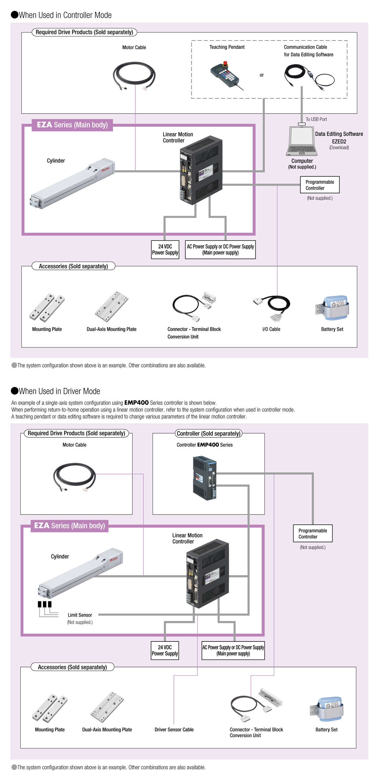
System Configuration