AC Speed Control Motors DSC Series
DSCI590JCM-GAR200V
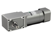
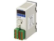
Geared Motor/Control Circuit
This product is currently no longer available for sale.
| Product Classification | Product Name | List Price | Shipping Date |
|---|---|---|---|
| Geared Motor / Control Circuit | DSCI590JCM-GAR200V | - | Discontinued Product (31.3.2021 discontinued) |
Included
- Geared Motor, Control Circuit, Capacitor, Capacitor Cap, Mounting Screws, Parallel Key, External Speed Potentiometer
Specifications
Dimensions
Data Download
Other Specifications
Common Specifications
| Item | Specifications | |
|---|---|---|
| Speed Setting Methods | Select one of the following setting methods.
|
|
| Acceleration Time and Deceleration Time Setting Range |
0.2~15.0 seconds (0.0~15.0 seconds: It can be set when the deceleration control is OFF.) Acceleration time/deceleration time varies with the load condition of the motor. |
|
| Function | Monitoring Mode | Rotation speed, operation data number, alarm code, warning code, I/O monitor |
| Data Mode | Speed, acceleration time, deceleration time, initialization | |
| Parameter Mode | Gear ratio, speed increasing ratio, fixed display for bottom row, prevention of operation at power-on alarm, external speed command input, external speed command voltage selection, external speed command offset, upper and lower speed limits, gear control, break type, input function selection, output function selection, motor lock detection time, motor rotation direction, reset | |
| Test Mode | JOG operation, releasing of the electromagnetic brake | |
| Other | Lock data editing | |
| Control Power Supply | 24 VDC±10 % 0.15 A min. | |
| Input Signals | Photocoupler Input Input Resistance: 4.7 kΩ Arbitrary signal assignment to IN0∼IN5 input (6 points) is possible. [ ]: Initial Setting [FWD], [REV], [M0], [M1], [ALARM-RESET], [FREE], EXT-ERROR Sink Input/Source Input…Can be switched using the Selection Switch: Factory Setting Sink Input |
|
| Output Signals | Photocoupler and Open-Collector Output External Power Supply: 4.5∼30 VDC, 40 mA max. Arbitrary signal assignment to OUT0, OUT1 output (2 points) is possible. [ ]: Initial Setting [SPEED-OUT], [ALARM-OUT], TH-OUT, WNG Sink Output/Source Output… Supported through external wiring |
|
| Protective Function | When the following protective functions are activated, output to the motor is shut down, the electromagnetic brake is engaged and the motor stops. The alarm output will be switched to OFF. At the same, the alarm code will be displayed on the operation panel and the Alarm LED will light up. Alarm Types: Motor overheat, motor lock, overspeed, EEPROM error, prevention of operation at power-on, external stop |
|
| Permissible Continuous Operation Time while Deceleration Control is ON | 25 W, 40 W | Permissible Continuous Operation Time: 1 minute Operating Duty: 50 % max. (Example: 1 minute operating, 1 minute stopped) |
| 90 W | Permissible Continuous Operation Time: 1 minute Operating Duty: 33 % max. (Example: 1 minute operating, 2 minutes stopped) |
|
| Maximum Extension Distance | 10.5 m between motor and controller (including 0.5 m motor cable) | |
General Specifications
| Item | Motor | Speed Controller | |
|---|---|---|---|
| Insulation Resistance | 100 MΩ or more when a 500 VDC megger is applied between the windings and the case after continuous operation under normal ambient temperature and humidity. | 100 MΩ min. when a 500 VDC megger is applied between the main circuit terminal and the control circuit terminal, between the main circuit terminal and the case, and between the main circuit terminal and FG after continuous operation under normal ambient temperature and humidity. | |
| Dielectric Strength | No abnormality is observed when 1.5 kVAC at 50 Hz or 60 Hz applied between the coils and case for 1 minute after continuous operation under normal ambient temperature and humidity. | No abnormality is observed when 1.9 kVAC is applied at 50 Hz or 60 Hz between the main circuit terminal and the control circuit terminal and between the main circuit terminal and the case, and when 1.5 kVAC is applied at 50 Hz or 60 Hz between the main circuit terminal and FG, for 1 minute after continuous operation under normal ambient temperature and humidity. | |
| Temperature Rise | Winding temperature rise is 80 °C max. measured by the resistance change method after continuous operation with no load under normal ambient temperature and humidity. | - | |
| Overheat Protective Device | Built-in Thermal Protector (Automatic Return Type) Open: 130±5 ℃, Reset: 85±20 ℃ |
- | |
| Operating Environment | Ambient Temperature | 0~+50 °C (Non-freezing) | 0~+40 °C (Non-freezing) |
| Ambient Humidity | 85 % max. (Non-condensing) | ||
| Altitude | Up to 1000 m above sea level | ||
| Atmosphere | No corrosive gases or dust. Should not be exposed to water or oil. Cannot be used in a radioactive area, magnetic field, vacuum, or other special environments. | ||
| Vibration | Not subject to continuous vibration or excessive shock in conformance with JIS C 60068-2-6, "Sine-wave vibration test method" Frequency Range: 10∼55 Hz, Half Amplitude: 0.15 mm, Sweep Direction: 3 directions (X, Y, Z), Number of Sweeps: 20 times |
||
| Storage Conditions* | Ambient Temperature | -25 ℃~+70 ℃ (Non-freezing) | |
| Ambient Humidity | 85 % max. (Non-condensing) | ||
| Altitude | Up to 3000 m above sea level | ||
| Atmosphere | No corrosive gases or dust. Should not be exposed to water or oil. Cannot be used in a radioactive area, magnetic field, vacuum, or other special environments. | ||
| Thermal Class | 130(B) | - | |
| Degree of Protection | IP20 | IP20 | |
- *The value for storage condition applies to short periods such as the period during transport.
Note
- Do not measure insulation resistance or perform a dielectric strength test while the motor and speed controller are connected.
Permissible Radial Load and Permissible Axial Load
| Gear Ratio | 5 | 7.5 | 10 | 15 | 20 | 25 | 30 | 40 | 50 | 60 | 75 | 100 | 120 | 150 | 200 | 240 | ||
|---|---|---|---|---|---|---|---|---|---|---|---|---|---|---|---|---|---|---|
| Permissible Radial Load [N] |
Hollow Shaft* | 10 mm From Mounting Surface | 1200 |
2200 |
||||||||||||||
| 20 mm From Mounting Surface | 1100 |
2000 |
||||||||||||||||
| Solid Shaft | 10 mm From the End of the Output Shaft | 900 |
1700 | |||||||||||||||
| 20 mm From the End of the Output Shaft | 1000 |
1850 | ||||||||||||||||
| Permissible Axial Load [N] | 350 | |||||||||||||||||
Standards
Regulations and Standards Materials
Documents about compliance with regulations and standards can be downloaded from the "Data Download" tab on the product details page.
(The types of files available for download vary by product.)
Explanations of the Global Laws, Regulations and Standards can be found here.
Information about our compliance with safety standards for each of our product models can be found here.
Hazardous Substances
The product does not contain any substances (10 substances) exceeding the regulation values of the RoHS Directive (2011/65/EU, 2015/863/EU).
For more information about compliance with regulations on chemical substances in Oriental Motor's Products, click here.
System Configuration
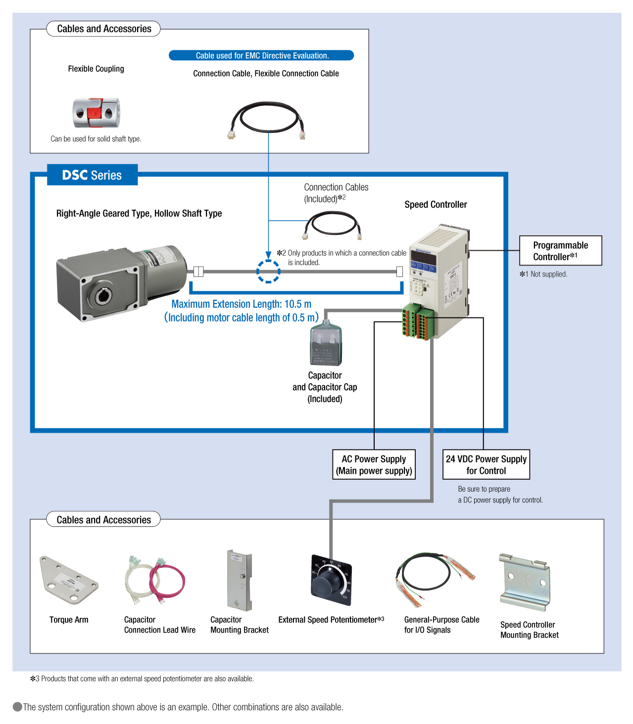
Cables and Accessories
close

close