Electromagnetic Brake Motors
4IK25SMB-15S
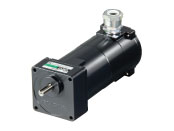
Combi geared motor
This product is currently no longer available for sale.
| Product Classification | Product Name | List Price | Shipping Date |
|---|---|---|---|
| Combi geared motor | 4IK25SMB-15S | - | Discontinued Product (1.4.2015 discontinued) |
Included
- Motor, Gearhead, Mounting Screws, Parallel Key, Operating Manual
Specifications
Characteristics
Starting and Braking Characteristics (Reference values)
Starting and Braking Characteristics (Reference values)
Data Download
Other Specifications
General Specifications
| Item | Specifications |
|---|---|
| Insulation Resistance | After rated operation at normal ambient temperature and humidity, the measurement between the coils and the case is 100 MΩ min. using a 500 VDC megger. |
| Dielectric Strength | No abnormality is observed even with an application of 1.5 kVAC at 50 Hz between the coils and the case for 1 minute after rated operation at normal ambient temperature and humidity. |
| Temperature Rise | A gearhead or equivalent heat sink* is connected to the motor and the winding temperature rise is measured at 80 °C max. using the resistance change method after continuous rated operation under normal ambient temperature and humidity. (Three-Phase type is 70 °C max.) |
| Thermal Class | 130 (B) |
| Overheat Protective Device | 6 W Type: Impedance protection Other Types: Built-in thermal protector (automatic return type) Open: 130 ± 5 °C, Return: 90 ± 15 °C (40 W Type: 82 ± 15 ℃) |
| Operating Ambient Temperature | Single-phase 100 VAC, single-phase 200 VAC, three-phase 200 VAC: -10~+50 °C (Non-freezing) Other voltages: -10~+40 °C (Non-freezing) |
| Operating Ambient Humidity | 85 % max. (Non-condensing) |
| Degree of Protection | IP65 (excluding mounting surface of the round shaft type) |
- *Heat sink size (Material: Aluminum)
| Motor Type (Output power) | Size (mm) | Thickness (mm) |
|---|---|---|
| 6 W Type | 115 x 115 | 5 |
| 15 W Type | 125 x 125 | |
| 25 W Type | 135 x 135 | |
| 40 W Type | 165 x 165 |
Permissible Radial Load and Permissible Axial Load of Gearhead
| Product Name | Gear Ratio | Maximum Permissible Torque N·m |
Permissible Radial Load N | Permissible Axial Load N |
|
|---|---|---|---|---|---|
| From Shaft End 10 mm |
From Shaft End 20 mm |
||||
| 2GN□S | 3~18 | 3.0 | 50 | 80 | 30 |
| 25~180 | 120 | 180 | |||
| 3GN□S | 3~18 | 5.0 | 80 | 120 | 40 |
| 25~180 | 150 | 250 | |||
| 4GN□S | 3~18 | 8.0 | 100 | 150 | 50 |
| 25~180 | 200 | 300 | |||
| 5GN□S | 3~18 | 10 | 250 | 350 | 100 |
| 25~180 | 300 | 450 | |||
System Configuration
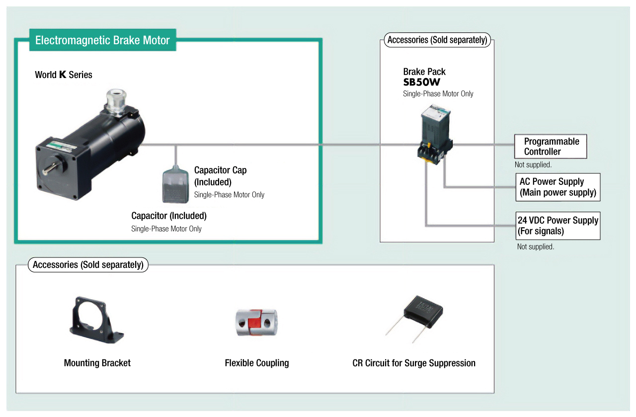
Cables and Accessories
close
close