FE100/FE200
FE200C
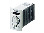
Control Circuit
This product is currently no longer available for sale.
| Product Classification | Product Name | List Price | Shipping Date |
|---|---|---|---|
| Control Circuit | FE200C | - | Discontinued Product (21.2.2014 discontinued) |
Included
- Control Circuit, Operating Manual
Specifications
Data Download
Other Specifications
Common Specifications
| Product Name | FE100A | FE100C | FE100S | FE200A | FE200C | FE200S | |
|---|---|---|---|---|---|---|---|
| Maximum Applicable Motor Capacitance W | 100 | 200 | |||||
| Output | Rated Output Power Voltage V | Three-Phase 200 VAC (depending on power supply voltage and load conditions) | |||||
| Rated Output Current A | 0.7 | 1.4 | |||||
| Power Supply Input | Rated Voltage V | Single-Phase 100-120 ±10% |
Single-Phase 200-240 ±10% |
Three-Phase 200-240 ±10% |
Single-Phase 100-120 ±10% |
Single-Phase 200-240 ±10% |
Three-Phase 200-240 ±10% |
| Rated Frequency Hz | 50/60 ±5% | ||||||
| Control Characteristics and Performance | Control Method | Sinusoidal PWM Method (V/f Control) | |||||
| Speed Setting Range | 6.6~80 Hz (200~2400 r/min) | ||||||
| Acceleration and Deceleration Time | 0.1~30 s (at 80 Hz speed setting) | ||||||
| Speed Setting Method | Speed Potentiometer on the front face of the Inverter/DC Voltage Input (0~10 VDC) | ||||||
| Voltage and Frequency Characteristics | Rotary switch to select according to motor output power | ||||||
| Function | Input Signals | Photocoupler Input: Input Resistance 3.3kΩ Operates with Internal Power Supply +15V RUN/STOP, FWD/REV, Alarm Reset |
|||||
| Output Signals | Open Collector Output: 26.4V DC 10mA max. Output during operation, alarm output |
||||||
| Setting Speed Display | Displays the setting speed *1 of the motor. | ||||||
| Remote/Local Switching ("RUN/STOP" and "FWD/REV") |
It can be switched to either operation by the RUN/STAND-BY switch or by an external input signal. (Factory Setting: Local) |
||||||
| Carrier Frequency Switching | Switch when you want to reduce the leakage current from the cable between the inverter and the motor. (Factory Setting: 15 kHz) |
||||||
| Sink/Source Switching | It can be switched to either a sink input with 0 V common or a source input with 24 V common. (Factory Setting: Sink) |
||||||
| Frequency/Rotation Speed Display Switching | The display on the speed display can be switched to the setting frequency or setting speed. (Factory Setting: Frequency) |
||||||
| Rotation speed display gear ratio switching *2 | The setting speed displayed on the speed display can be switched to a speed that matches the gear ratio. It can be set to 96 different settings with 2 rotary switches. (Factory Setting: Gear Ratio 1:1) |
||||||
| Protective Function |
If any of the following protective functions are activated, the base blocking action will be used to stop the motor.
|
||||||
| Wiring Distance Between Inverter and Motor | Maximum length 20 m (when using connection cable CC20AC04) | ||||||
| Cooling Conditions | Natural Air Cooling | ||||||
| Display | 7 seg Display | Setting speed, alarm code | |||||
| LED indication | POWER, Setting Speed Unit of display (r/min, Hz) | ||||||
| Mass kg | 0.4 | 0.5 | |||||
- *1
- This is different from the motor shaft rotation speed.
- *2
- This function is disabled when the frequency is displayed.
- *3
- Motor output power 6 W type is excluded.
General Specifications
| Item | Specifications | |
|---|---|---|
| Insulation Resistance | After continuous operation at normal ambient temperature and humidity, the value measured with a 500 VDC megger between the main circuit terminal and the ground terminal (control circuit terminal) is min. 100 MΩ. |
|
| Dielectric Strength | After continuous operation at normal ambient temperature and humidity, no abnormality is observed even if 50 Hz or 60 Hz, 1.85 kVAC is applied between the main circuit terminal and the ground terminal (control circuit terminal) for 1 minute. |
|
| Operating Environment | Ambient Temperature | -10~+50°C (Non-freezing) |
| Ambient Humidity | 85 % max. (Non-condensing) | |
| Atmosphere | No corrosive gases or dust | |
| Degree of Protection | IP10 (IP20 on the front face of the inverter) | |
Note
- Do not perform an insulation resistance measurement or a dielectric strength test while the motor and inverter are connected.
close