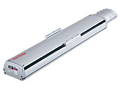
Electric Linear Slide EZ-limo AC Servo Motor Equipped EZX Series
EZX9LH-80MWA
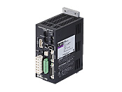
Actuator/Control Circuit
| Product Classification | Product Name | List Price | Shipping Date |
|---|---|---|---|
| Actuator / Control Circuit | EZX9LH-80MWA | €1,113.00 | Discontinued Product (1.4.2015 discontinued) |
Included
- Actuator, Control Circuit, Regeneration Unit (RGB100), Battery (PAEZX-BT), Control I/O Connector, Sensor I/O Connector, Main Power Connector, Main Power Connector Lever, Control Power Supply Connector, Operating Manual
Specifications
Other Specifications
General Specifications (Motor)
Values are after rated operation at normal ambient temperature and humidity.
| Item | Specifications |
|---|---|
| Insulation Resistance |
100 MΩ or more when 500 VDC megger is applied between the following places.
|
| Dielectric Strength |
No abnormalities observed with application for 1 minute at the following points.
|
| Operating Ambient Temperature | 0~+40 °C (Non-freezing) |
| Operating Ambient Humidity | 85 % max. (Non-condensing) |
Circuit Specifications (Controller Mode)
Controller Mode
| Product Line | Stored data type | ||
|---|---|---|---|
| Number of Control Axes | single axis | ||
| Power Supply Input | Control Power Supply | 24 VDC±5 % 1.0 A [0.5 A for controller only (see +0.2 A with teaching pendant, +0.3 A with electromagnetic brake)]. | |
| Main Power Supply | Voltage | Single-phase 100-115 VAC -15 %~+10 %, Single-phase 200-230 VAC -15 %~+10 % | |
| Frequency | 50/60 Hz | ||
| Current | Single-Phase 100-115 VAC: 4.6 A (maximum 9.2 A), Single-Phase 200-230 VAC: 2.8 A (maximum 5.6 A) | ||
| Positioning Data |
Setting Mode | Absolute mode (absolute-position specification), incremental mode (relative-position specification) | |
| Setting Number | 63 Steps | ||
| Setting Method | Setting by accessory teaching pendant (EZT1) or data editing software (EZED2) (Stored in EEPROM) | ||
| Positioning Control |
Method | Sequential positioning, Data-select positioning | |
| Traveling Amount Setting Range | -8388.608~+8388.607 mm (in 0.001 mm units) | ||
| Starting Speed Setting Range | 0.001~250.000 mm/s (in 0.001 mm/s units) | ||
| Operating Speed Setting Range | 0.001~2000.000 mm/s (in 0.001 mm/s units) | ||
| Acceleration/Deceleration Rate Setting Range | 0.01~20.00 m/s2 (in 0.01 m/s2 units) | ||
| Control Mode |
|
||
| Operation Mode |
|
||
| Input Signal/Input Mode | START, STOP, HOME/PRESET, FREE, M0~M5, REQ, ACL/CK 24 VDC Photocoupler insulated input, Input resistance 4.7 kΩ FWD/FP, RVS/RP 5 VDC Photocoupler insulated input Input resistance 200 Ω or 24 VDC Photocoupler insulated input Input resistance 2.7 kΩ |
||
| Output Signal/Output Mode | ALM, END/OUTR, MOVE/READY, AREA/OUT0, OUT1, ASG1, BSG1, ASG2, BSG2 Photocoupler-connected transistor output (24 VDC 15 mA max.), Line driver output |
||
| Sensor Input/Input Mode | +LS, −LS, HOMELS 24 VDC Photocoupler insulated input, Input resistance 4.7 kΩ |
||
| Protective Function | Excessive position deviation, overcurrent protection, overvoltage protection, overheat protection, overload, motor overheat protection, sensor error, overspeed, non-volatile memory error, etc. | ||
| Indicator (LED) | OPERATION, ALARM, CHARGE | ||
| Cooling Method | Natural Cooling Method | ||
| Mass | 0.95 kg | ||
Circuit Specifications (Driver Mode)
Driver Mode
| Power Supply Input | Control Power Supply | 24 VDC±5 % 1.0 A [0.5 A for controller only (see +0.2 A with teaching pendant, +0.3 A with electromagnetic brake)]. | |
|---|---|---|---|
| Main Power Supply | Voltage | Single-phase 100-115 VAC -15 %~+10 %, Single-phase 200-230 VAC -15 %~+10 % | |
| Frequency | 50/60 Hz | ||
| Current | Single-Phase 100-115 VAC: 4.6 A (maximum 9.2 A), Single-Phase 200-230 VAC: 2.8 A (maximum 5.6 A) | ||
| Maximum Response Frequency | 500kHz | ||
| Input Signal/Input Mode | 24 VDC Photocoupler insulated input, Input resistance 4.7 kΩ | ||
| Output Signal/Output Mode | READY, END/OUTR, ALM, ZSG/OUT0, OUT1, ASG1, BSG1, ASG2, BSG2 Photocoupler-connected transistor output (24 VDC 15 mA max.), Line driver output |
||
| Protective Function | Excessive position deviation, overcurrent protection, overvoltage protection, overheat protection, overload, motor overheat protection, sensor error, overspeed, non-volatile memory error, etc. | ||
| Indicator (LED) | OPERATION, ALARM, CHARGE | ||
| Cooling Method | Natural Cooling Method | ||
| Mass | 0.95 kg | ||
Circuit General Specifications
Values are after rated operation at normal ambient temperature and humidity.
| Item | Specifications |
|---|---|
| Insulation Resistance | 100 MΩ or more when 500 VDC megger is applied between the following places. Between I/O connector and main power supply input terminal, motor cable connector, battery connector Between control power supply input terminal and main power supply input terminal, motor cable connector, battery connector Between protective earth terminal and main power supply input terminal, motor cable connection connector, battery connector |
| Dielectric Strength |
No abnormalities observed with application for 1 minute at the following points.
|
| Operating Ambient Temperature | 0~+40 °C (Non-freezing) |
| Operating Ambient Humidity | 85 % max. (Non-condensing) |
Attached Battery Specifications
| Item | Product Name: PAEZX-BT |
|---|---|
| Battery Type | Lithium thionyl chloride battery |
| Nominal Voltage | 3.6 V |
| Rated Capacity | 1700 mAh |
| Mass | 0.014 kg |
| Lifetime | 4 years* |
| Data Retention Period | 2 years* |
| Operating Ambient Temperature | 0~+40 °C (Non-freezing) |
| Operating Ambient Humidity | 85 % max. (Non-condensing) |
- *At an ambient temperature of 20 °C
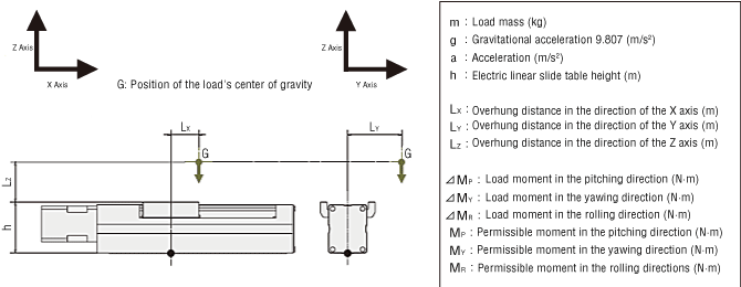
Calculating Load Moment
When a load is transported with an electric linear slide or electric cylinder (a unit equipped with shaft guide covers only), the load moment acts on the linear guide/shaft guide if the position of the load's center of gravity is offset from the center of the table/center of the shaft guide. The direction of action applies to the directions for pitching (MP), yawing (MY), and rolling (MR), depending on the position of the offset.
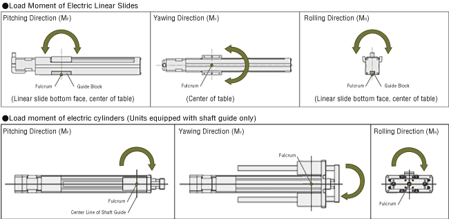
Even though the selected electric actuators satisfy the load mass and positioning time requirements, when the center of gravity of the load is overhung from the table's center/shaft guide’s center, the run life may decrease as a result of the load moment. Load moment calculations must be completed and whether the conditions are within specifications values must be checked. The moment applied under static conditions is the static permissible moment. The moment applied under movement is the dynamic permissible moment, and both must be checked.
Calculate the load moment of the electric linear slides and electric cylinders (units equipped with shaft guide covers only) based on loads that are applied. Check that the static permissible moment and dynamic permissible moment are within limits and check that strength is sufficient.
- *For more information on calculating static permissible moment and dynamic permissible moments, click here.
Load Moment Formula
When there are several overhung loads, etc., it is determined by the sum of moments from all loads.
For Multiple Loads (n)
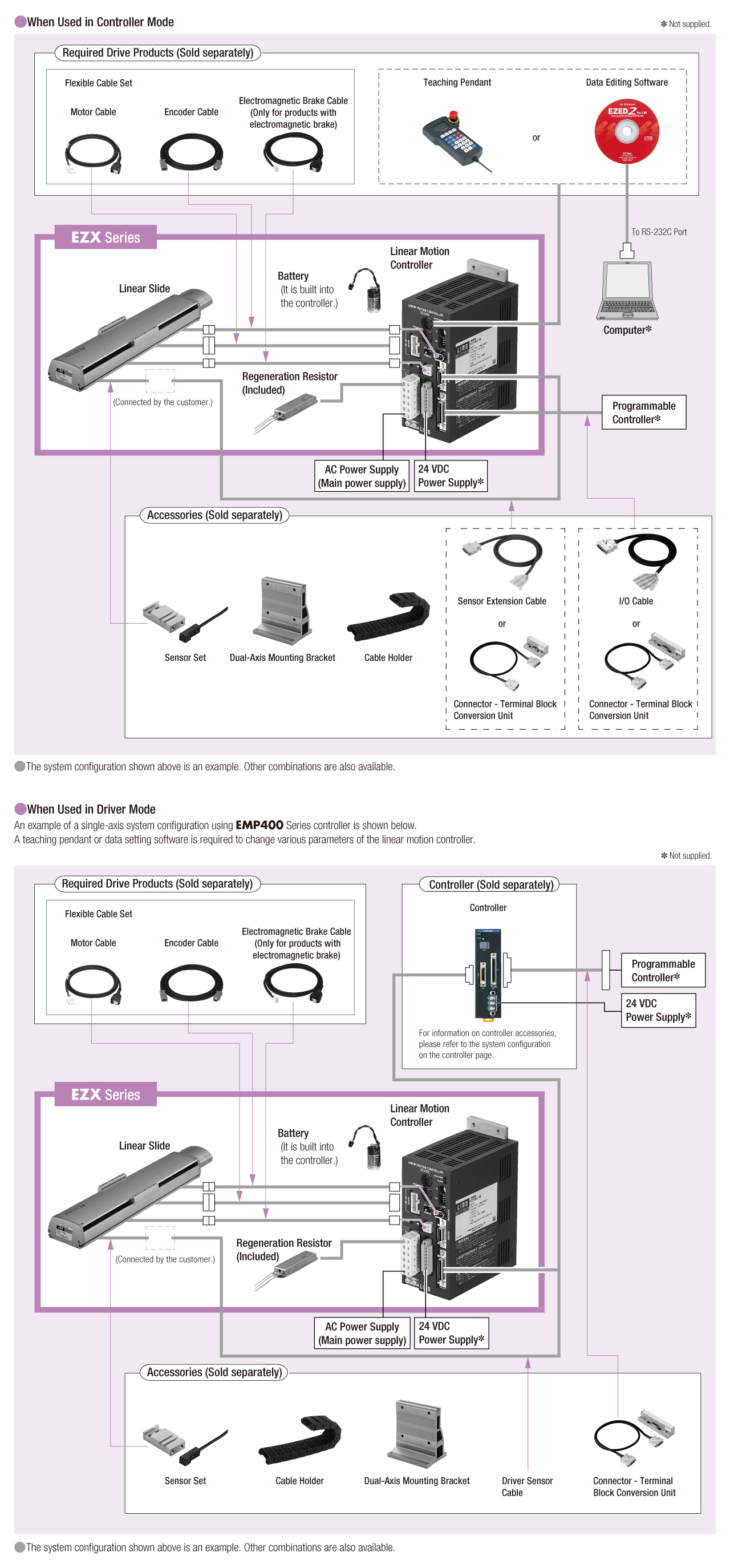
System Configuration