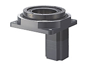
Hollow Rotary Actuators DG Series
DG200R-ASMA
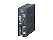
Actuator/Control Circuit
This product is currently no longer available for sale.
| Product Classification | Product Name | List Price | Shipping Date |
|---|---|---|---|
| Actuator / Control Circuit | DG200R-ASMA | - | Discontinued Product (1.4.2018 discontinued) |
Included
- Actuator, Control Circuit, I/O signal Connector, Mounting Brackets for Control Circuit (with screws), Surge Suppressor, Operating Manual
Specifications
Other Specifications
Driver Circuit Specifications
| Product Name | ASD10A-K | ASD13B-A | ASD24A-A | ASD30E-A | ASD12A-C | ASD20A-C | ASD12A-S | ASD20A-S | |
|---|---|---|---|---|---|---|---|---|---|
| Power Supply Input |
Voltage | 24 VDC±10 % |
Single-Phase 100-115 VAC
+10 %
-15 % |
Single-Phase 200-230 VAC
+10 %
-15 % |
Three-Phase 200-230 VAC
+10 %
-15 % |
||||
| Frequency | - | 50/60 Hz | 50/60 Hz | 50/60 Hz | |||||
| Current | 1.0 A | 3.3 A | 5 A | 6.5 A | 3 A | 4.5 A | 1.5 A | 2.4 A | |
| Maximum Input Pulse Frequency | 250 kHz (at 50 % duty cycle) | ||||||||
| Input Signal |
Input Mode | Photocoupler input, input resistance 220 Ω, input current 7~20 mA | |||||||
| CW pulse (Pulse) |
CW direction operation command pulse signal (operation command pulse signal when 1-pulse input mode) Pulse width 1 μs min., rise/fall time 2 μs max. Negative logic pulse input |
||||||||
| CCW pulse (Rotation Direction) |
CCW direction operation command pulse signal (rotation direction signal when 1-pulse input mode is used) Pulse width 1 μs min., rise/fall time 2 μs max. Negative logic pulse input |
||||||||
| Alarm Clear |
Input when protective function is activated to clear the alarm status. | ||||||||
| All Windings Off | When the photocoupler is ON, the output current to the motor part is turned OFF and the output table can be moved by hand. When the photocoupler is OFF, the current is supplied to the motor part. |
||||||||
| Resolution Select | When the photocoupler ON, the resolution is 10 times the resolution at power on. When the photocoupler is OFF, the resolution is the resolution at power on. This function is enabled when the resolution select switch is set to 9000 P/R or 18000 P/R. |
||||||||
| Output Signal |
Output Mode | Photocoupler and open-collector output, external use conditions: 30 VDC, 15 mA max. (Positioning completion, alarm, timing [ASD10A-K only]) Transistor and open-collector output, external use conditions 30 VDC max., 15 mA max. (Feedback pulse phase A and B, timing [except ASD10A-K]) Line driver output 26C31 or equivalent (timing, feedback pulse phase A and B) [except ASD10A-K] |
|||||||
| Timing | Output each time the output table rotates by 0.4°.(Photocoupler: ON) Available in 500 Hz max. in maximum speed input pulse frequency. |
||||||||
| Alarm | Output when the protective function is activated.(Photocoupler: OFF) Alarm outputs (Blinking red LED), while at the same time, the actuator comes to a coasting stop. |
||||||||
| Positioning Complete |
Outputs on positioning completion.(Photocoupler: ON) Outputs when the pulse speed is 500 Hz max., and the output table is within ±0.1˚ of the command position. |
||||||||
| Phase A, Phase B Pulse Output |
Output at the resolution when the driver is powered on. The phase difference between phase A and phase B is 90˚ in electrical angle. There is a time lag of maximum 1 ms relative to the actual motion of the actuator. Use to confirm the stop position. |
||||||||
| Protective Function | Overheat protection, overload protection, overvoltage protection, speed error protection, overcurrent protection, overspeed, EEPROM data error, sensor error, system error (ASD10A-K does not have overheat protection or overcurrent protective functions) |
||||||||
| Degree of Protection | IP00 | IP10 | |||||||
| Indicator (LED) | Operation display (green LED), alarm display (red LED) | ||||||||
| Cooling Method | Natural cooling method | ||||||||
| Mass | 0.25 kg | 0.8 kg | |||||||
Note
- The CW input and CCW input of the driver input signal, and the rotation direction of the output table are opposite.
When the input is CW, the output table rotates counterclockwise. When the input is CCW, the output table rotates clockwise.
Driver Circuit Specifications
| Product Name | ASD13B-AD | ASD24A-AD | ASD30E-AD | ASD12A-CD | ASD20A-CD | ASD12A-SD | ASD20A-SD | |
|---|---|---|---|---|---|---|---|---|
| Power Supply Input | Voltage |
Single-Phase 100-115 VAC
+10 %
-15 % |
Single-Phase 200-230 VAC
+10 %
-15 % |
Three-Phase 200-230 VAC
+10 %
-15 % |
||||
| Frequency | 50/60 Hz | |||||||
| Current | 3.3 A | 5 A | 6.5 A | 3 A | 4.5 A | 1.5 A | 2.4 A | |
| Speed and Position Control Command | Stored Data | |||||||
| Input Signals | Photocoupler input, Input resistance 4.7 kΩ, 24 VDC±10 % 5 mA | |||||||
| Output Signals | Photocoupler and open-collector output External use conditions 30 VDC 15 mA max. | |||||||
| Data-select positioning | 61 data maximum (stored in EEPROM) | |||||||
| Positioning Control | Incremental (relative distance specification method) / Absolute (absolute position specification method) One-shot operation / Linked operation (maximum 61 links) -8388608 steps~+8388607 steps per data Operating speed 10 Hz~500 kHz (in 10 Hz increments) Acceleration/deceleration rate*0.1~1000 ms/kHz (in 0.1 ms/kHz units) |
|||||||
| Return-to-Mechanical Home Operation | Perform return-to-home operation from the entire range using mechanism part detection signal (+LS, -LS, HOMELS). | |||||||
| Operation Mode | Positioning operation, Return-to-mechanical home operation, Continuous operation, Return-to-electrical home operation | |||||||
| Protective Function | Overheat protection, overload protection, overvoltage protection, overcurrent protection, overspeed, EEPROM data error Sensor error, excessive position deviation, rotor rotation error at initiation, E-STOP detection, limit sensor logic error Limit sensor reverse connection, return-to-mechanical home operation error, hard limit detection, out of software limit range, operation data invalid |
|||||||
| Other Functions | Motor part resolution setting function (dividing/multiplication, electronic gear), current setting function, speed filter function, motor direction setting function, external stop function, sensor logic setting function, overtravel function, software overtravel function, alarm trace-back function, display function, alarm code output function, and teaching function, I/O test function | |||||||
| Degree of Protection | IP10 | |||||||
| Indicator (LED) | Operation display (Green LED), Alarm display (Red LED) | |||||||
| Cooling Method | Natural Cooling Method | |||||||
| Mass | 0.8 kg | |||||||
- * The acceleration rate and deceleration rate can be set separately.
General Specifications
Values are after rated operation at normal ambient temperature and humidity.
| Item | Motor | Driver |
|---|---|---|
| Insulation Class | Class B (130 °C) [UL/CSA Standards are Class A (105 °C)] | - |
| Insulation Resistance |
100 MΩ or more when a 500 VDC megger is applied between the following places.
|
100 MΩ or more when a 500 VDC megger is applied between the following places.
|
| Dielectric Strength |
No abnormalities observed with application for 1 minute at the following points.
|
No abnormalities observed with application for 1 minute at the following points.
|
| Operating Ambient Temperature | 0~+50 °C (Non-freezing) When home-sensor set (accessory) is installed: 0~+40 °C (Non-freezing) |
[ASD13B-A, ASD24A-A, ASD30E-A, ASD12A-C, ASD20A-C, ASD12A-S, ASD20A-S] 0~+50 °C (Non-freezing) [ASD10A-K, ASD13B-AD, ASD24A-AD, ASD30E-AD, ASD12A-CD, ASD20A-CD, ASD12A-SD, ASD20A-SD] 0~+40 °C (Non-freezing) |
| Operating Ambient Humidity | 85 % max. (Non-condensing) | |
Note
- Do not measure insulation resistance or perform a dielectric strength test the actuator and driver are connected.
System Configuration
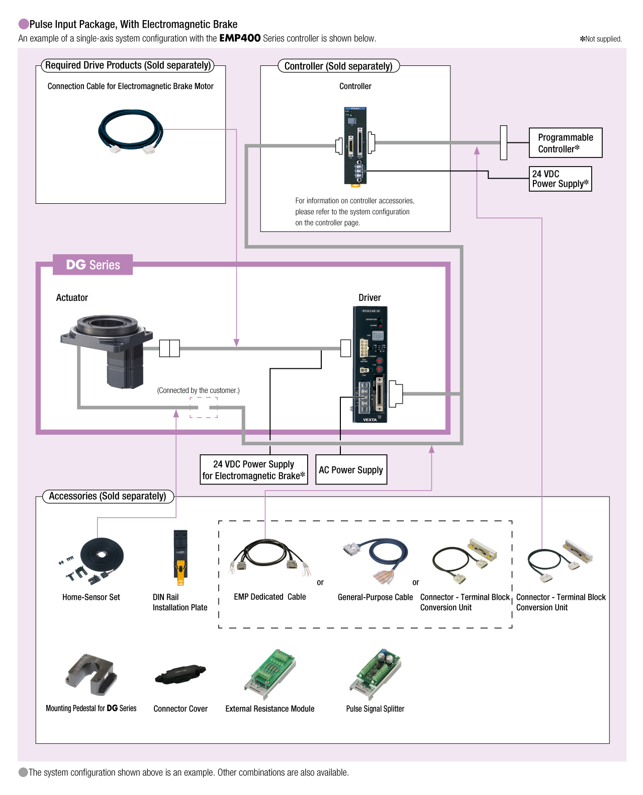
Cables and Accessories
close