Brushless Motors BLE Series
BLE46C15F-1
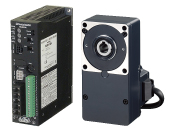
Gearhead / Motor / Control Circuit
| Product Classification | Product Name | List Price | Shipping Date |
|---|---|---|---|
| Gearhead / Motor / Control Circuit | BLE46C15F-1 | - | Discontinued Product (31.3.2024 discontinued) |
Included
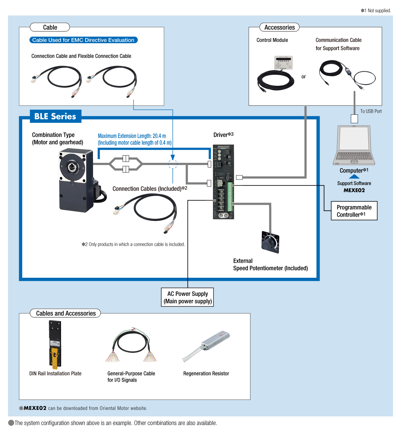
- Motor, Control Circuit, Gearhead, Connection Cable, External Speed Potentiometer (with Signal Line), Mounting Screws, Parallel Key, Safety Cover (with Screws), Operating Manual
Specifications
Characteristics

Speed - Torque Characteristics
Dimensions

Motor/Gearhead

Control Circuit

Connection Cable
Data Download
Other Specifications
Common Specifications
- Standard Model: These specifications apply when using the basic motor and driver package.
- Extended Functions: These specifications apply when a control module (OPX-2A) or support software (MEXE02) is used.
| Item | Standard Model | Extended Functions |
|---|---|---|
| Speed Setting Methods | Select one of the following methods.
|
Select one of the following methods.
|
| Acceleration Time and Deceleration Time | Setting using Acceleration Time and Deceleration Time Potentiometer: 0.2∼15 sec. (3000 r/min at no load) |
Select one of the following methods.
|
| Multi-Speed Setting Methods |
2-Speed:
1 speed set by the internal speed potentiometer and 1 speed set by the external speed potentiometer (20 kΩ, 1/4 W) or external DC voltage (0∼5 VDC or 0∼10 VDC).
|
Select one of the following methods.
|
| Input Signals | Photocoupler Input Input Resistance: 5.1 kΩ Operated by Internal Power Supply: 17 VDC±10% Connectable External DC Power Supply: 24 VDC −15∼+20% Current 100 mA min. |
|
|
Forward input (FWD), Reverse input (REV), Stop mode selection input (STOP-MODE), Speed setting selection input (M0), Alarm reset input (ALARM-RESET), Electromagnetic brake release input (MB-FREE), Regeneration resistor thermal input (TH) |
Arbitrary signal assignment to general purpose input X0∼X6 (7 points) is possible Forward input (FWD), Reverse input (REV), Stop mode selection input (STOP-MODE), Speed setting selection input (M0, M1, M2), Alarm reset input (ALARM-RESET), Electromagnetic brake release input (MB-FREE), Regeneration resistor thermal input (TH),External Error Input (EXT-ERROR) |
|
| Output Signals | Open-Collector Output External Operating Condition: Voltage Control 4.5∼30.0 VDC Current 40 mA max. Speed Output: 5 mA min. |
|
| Speed Output (SPEED-OUT), Alarm Output 1 (ALARM-OUT 1) |
Arbitrary signal assignment to general purpose output Y0, Y1 (2 points) is possible. Speed output (SPEED-OUT), alarm output 1 (ALARM-OUT1), motor running output (MOVE), speed attainment output (VA), alarm output 2 (ALARM-OUT2), warning output (WNG), torque limiting output (TLC) |
|
| Protective Functions |
When the following protective functions are activated, the motor will coast to a stop, and the ALARM output will be turned off. The alarm LED of the driver will be blinking the number of times shown in parentheses.
|
|
| Maximum Extension Distance | 20.4 m between motor and driver | |
| Time Rating | Continuous | |
- *1
- *This is a 1-speed set by the internal speed potentiometer and 1-speed set by external speed potentiometer (20 kΩ, 1/4 W) or external DC voltage (0~5 VDC or 0~10 VDC).
- *2
- Limited to when EXT-ERROR is assigned using OPX-2A or MEXE02.
- *3
- This will only occur when using OPX-2A or MEXE02 in the "effective" setting. FBLⅡ Disabled during setting to compatibility mode.
- *4
- This will not occur with setting a torque limiting value less than 200% using OPX-2A or MEXE02.
General Specifications
| Item | Motor | Driver | |
|---|---|---|---|
| Insulation Resistance | 100 MΩ or more when a 500 VDC megger is applied between the windings and the case after continuous operation under normal ambient temperature and humidity. |
After continuous operation at normal ambient temperature and humidity, the measurement value between the power supply terminal and the protective earth terminal and the power supply terminal and the I/O terminal is 100 MΩ min. using a 500 VDC megger. |
|
| Dielectric Strength | No abnormality is observed even with an application of 1.5 kVAC at 50 Hz between the coils and the case for 1 minute after continuous operation at normal ambient temperature and humidity. |
No abnormality is observed even with an application of 1834 VAC at 50 Hz between the power supply terminal and the protective earth terminal or 3 kVAC at 50 Hz between the power supply terminal and the signal I/O terminal for 1 minute after continuous operation at normal ambient temperature and humidity. |
|
| Temperature Rise | After continuous operation at normal ambient temperature and humidity, the measured value using the thermocouple method is 50 °Cmax. for the temperature rise of the coils and 40 °C max. *1for the temperature rise on the case surface. |
After continuous operation at normal ambient temperature and humidity, the measurement value of the temperature rise of the heat sink is 50 °C max. using the thermocouple method. |
|
| Operating Environment | Ambient Temperature | 0∼+50°C (Non-freezing) | |
| Ambient Humidity | 85 % max. (Non-condensing) | ||
| Altitude | Up to 1000 m above sea level | ||
| Atmosphere | No corrosive gases or dust Cannot be used in a radioactive area, magnetic field, vacuum, or other special environments. | ||
| Vibration | Not subject to continuous vibration or excessive shock In conformance with JIS C 60068-2-6, "Sine-wave vibration test method" Frequency Range: 10~55 Hz, Half Amplitude: 0.15 mm, Sweep Direction: 3 directions (X, Y, Z), Number of Sweeps: 20 times |
||
| Storage Conditions*2 | Ambient Temperature | -25~+70°C (Non-freezing) | |
| Ambient Humidity | 85 % max. (Non-condensing) | ||
| Altitude | Up to 3000 m above sea level | ||
| Thermal Class | UL/CSA Standards: 105 (A), EN Standards: 120 (E) | − | |
| Degree of Protection | IP65 (Excluding the installation surface of the round shaft type and connectors) | IP20 | |
- *1
- Attach round shaft types to a heat sink (Material: aluminum) of one of the following sizes to maintain a motor case surface temperature of 90 °C max.
30 W Type: 115x115 mm (135x135 mm), 5 mm thickness Figures in parentheses are for the electromagnetic brake type.
60 W Type: 135x135 mm, 5 mm thickness
120 W Type: 165x165mm, 5mm thickness - *2
- The value for storage condition applies to short periods such as the period during transport.
Note
- Do not measure insulation resistance or perform a dielectric strength test the motor and driver are connected.
Torque Limiting Function
Using a control module (OPX-2A) or the support software (MEXE02) allows setting of motor output torque limits.
| Item | Specifications |
|---|---|
| Torque Limiting Setting Methods |
Select one of the following methods.
|
| Torque Limiting Setting Range |
Assuming that the rated torque of the motor is 100%, torque limiting value can be set in the following ranges (Initial Value 200%).
|
Note
- An error up to a max. of approximately ±20 % (at rated torque and rated speed) may occur between the setting value and generated torque due to the setting speed, power supply voltage and motor cable extension length.
Permissible Radial Load and Permissible Axial Load
Combination type with a parallel shaft gearhead
| Product Name | Gear Ratio | Permissible Radial Load | Permissible Axial Load N |
||
|---|---|---|---|---|---|
| From Shaft End 10 mm N |
From Shaft End 20 mm N |
||||
| BLE23■□S◇ | 5 | At 100~3000 r/min | 100 | 150 | 40 |
| At 4000 r/min | 90 | 110 | |||
| 10, 15, 20 | At 100~3000 r/min | 150 | 200 | ||
| At 4000 r/min | 130 | 170 | |||
| 30, 50, 100, 200 | At 100~3000 r/min | 200 | 300 | ||
| At 4000 r/min | 180 | 230 | |||
| BLE46■□S◇ | 5 | At 100~3000 r/min | 200 | 250 | 100 |
| At 4000 r/min | 180 | 220 | |||
| 10, 15, 20 | At 100~3000 r/min | 300 | 350 | ||
| At 4000 r/min | 270 | 330 | |||
| 30, 50, 100, 200 | At 100~3000 r/min | 450 | 550 | ||
| At 4000 r/min | 420 | 500 | |||
| BLE512■□S◇ | 5 | At 100~3000 r/min | 300 | 400 | 150 |
| At 4000 r/min | 230 | 300 | |||
| 10, 15, 20 | At 100~3000 r/min | 400 | 500 | ||
| At 4000 r/min | 370 | 430 | |||
| 30, 50, 100, 200 | At 100~3000 r/min | 500 | 650 | ||
| At 4000 r/min | 450 | 550 | |||
Combination type with a hollow shaft flat gearhead
| Product Name | Gear Ratio | Permissible Radial Load | Permissible Axial Load N |
||
|---|---|---|---|---|---|
| From the Gearhead Mounting Surface 10 mm N |
From the Gearhead Mounting Surface 20 mm N |
||||
| BLE23■□F◇ | 5, 10 | At 100~3000 r/min | 450 | 370 | 200 |
| At 4000 r/min | 410 | 330 | |||
| 15, 20, 30, 50, 100, 200 |
At 100~3000 r/min | 500 | 400 | ||
| At 4000 r/min | 460 | 370 | |||
| BLE46■□F◇ | 5, 10 | At 100~3000 r/min | 800 | 660 | 400 |
| At 4000 r/min | 730 | 600 | |||
| 15, 20, 30, 50, 100, 200 |
At 100~3000 r/min | 1200 | 1000 | ||
| At 4000 r/min | 1100 | 910 | |||
| BLE512■□F◇ | 5, 10 | At 100~3000 r/min | 900 | 770 | 500 |
| At 4000 r/min | 820 | 700 | |||
| 15, 20 | At 100~3000 r/min | 1300 | 1110 | ||
| At 4000 r/min | 1200 | 1020 | |||
| 30, 50, 100, 200 | At 100~3000 r/min | 1500 | 1280 | ||
| At 4000 r/min | 1400 | 1200 | |||
Round Shaft Type
| Product Name | Permissible Radial Load | Permissible Axial Load | |
|---|---|---|---|
| From Shaft End 10 mm N |
From Shaft End 20 mm N |
||
| BLE23■A◇ | 80 | 100 | Half of the motor mass or less |
| BLE46■A◇ | 110 | 130 | |
| BLE512■A◇ | 150 | 170 | |
Permissible Radial Load Calculation
The formula for calculating the permissible radial load varies depending on the mechanism.
When One Side of the Load Shaft is Not Supported by the Bearing Unit
The radial load is the most difficult mechanism. A Stepped Type Load Shaft is recommended.
| Product Name | Permissible Radial load W [N] |
|---|---|
| GFS2G□FR |
\(\begin{align} \mathrm{W} [\mathrm{N}] = \frac{36}{36 + \mathrm{Lp}} \times \mathrm{F}_0 [\mathrm{N}] \end{align}\)
|
| GFS4G□FR |
\(\begin{align} \mathrm{W} [\mathrm{N}] = \frac{40}{40 + \mathrm{Lp}} \times \mathrm{F}_0 [\mathrm{N}] \end{align}\)
|
| GFS5G□FR |
\(\begin{align} \mathrm{W} [\mathrm{N}] = \frac{50}{50 + \mathrm{Lp}} \times \mathrm{F}_0 [\mathrm{N}] \end{align}\)
|
| GFS6G□FR |
\(\begin{align} \mathrm{W} [\mathrm{N}] = \frac{60}{60 + \mathrm{Lp}} \times \mathrm{F}_0 [\mathrm{N}] \end{align}\)
|
When One Side of the Load Shaft is Supported by the Bearing Unit
| Product Name | Permissible Radial load W [N] |
|---|---|
| GFS2G□FR GFS4G□FR GFS5G□FR GFS6G□FR |
\(\begin{align} \mathrm{W} [\mathrm{N}] = \frac{\mathrm{B}}{\mathrm{B} - \mathrm{Lp}} \times \mathrm{F}_0 [\mathrm{N}] \end{align}\)
|
| Product Name | Rotation Speed | Gear Ratio | F0 [N] |
|---|---|---|---|
| GFS2G□FR | At 3~3000 r/min | 5, 10 | 570 |
| 15~200 | 630 | ||
| At 4000 r/min | 5, 10 | 520 | |
| 15~200 | 580 | ||
| GFS4G□FR | At 3~3000 r/min | 5, 10 | 1000 |
| 15~200 | 1500 | ||
| At 4000 r/min | 5, 10 | 910 | |
| 15~200 | 1370 | ||
| GFS5G□FR | At 3~3000 r/min | 5, 10 | 1080 |
| 15, 20 | 1550 | ||
| 30~200 | 1800 | ||
| At 4000 r/min | 5, 10 | 980 | |
| 15, 20 | 1430 | ||
| 30~200 | 1680 | ||
| GFS6G□FR | At 3~3000 r/min | 5, 10 | 1430 |
| 15, 20 | 1960 | ||
| 30~100 | 2380 | ||
| At 4000 r/min | 5, 10 | 1320 | |
| 15, 20 | 1810 | ||
| 30~100 | 2210 |
Standards
Regulations and Standards Materials
Documents about compliance with regulations and standards can be downloaded from the "Data Download" tab on the product details page.
(The types of files available for download vary by product.)
Explanations of the Global Laws, Regulations and Standards can be found here.
Information about our compliance with safety standards for each of our product models can be found here.
Hazardous Substances
The product does not contain any substances (10 substances) exceeding the regulation values of the RoHS Directive (2011/65/EU, 2015/863/EU).
For more information about compliance with regulations on chemical substances in Oriental Motor's Products, click here.
System Configuration