Brushless Motors Inverter Combination (750W/AC Power Supply Input)
BL2M6750CHP-5S
Motor


| Product Classification | Product Name | List Price | Shipping Date |
|---|---|---|---|
| Motor | BL2M6750CHP-5S | €690.00 | Up to 5 pcs Estimated Ship 5weeks |
• Specifications and various data of combination products may be shown on the combination product page. Please check the page of the combination product.
• A "dedicated connection cable" is available when using the motor in combination with an inverter made by other manufacturers.
Notice: The shipping date refers to the time of dispatch from the warehouse in Düsseldorf/Germany.
Included
- Motor: Mounting Screws, Parallel Key
Specifications
Dimensions
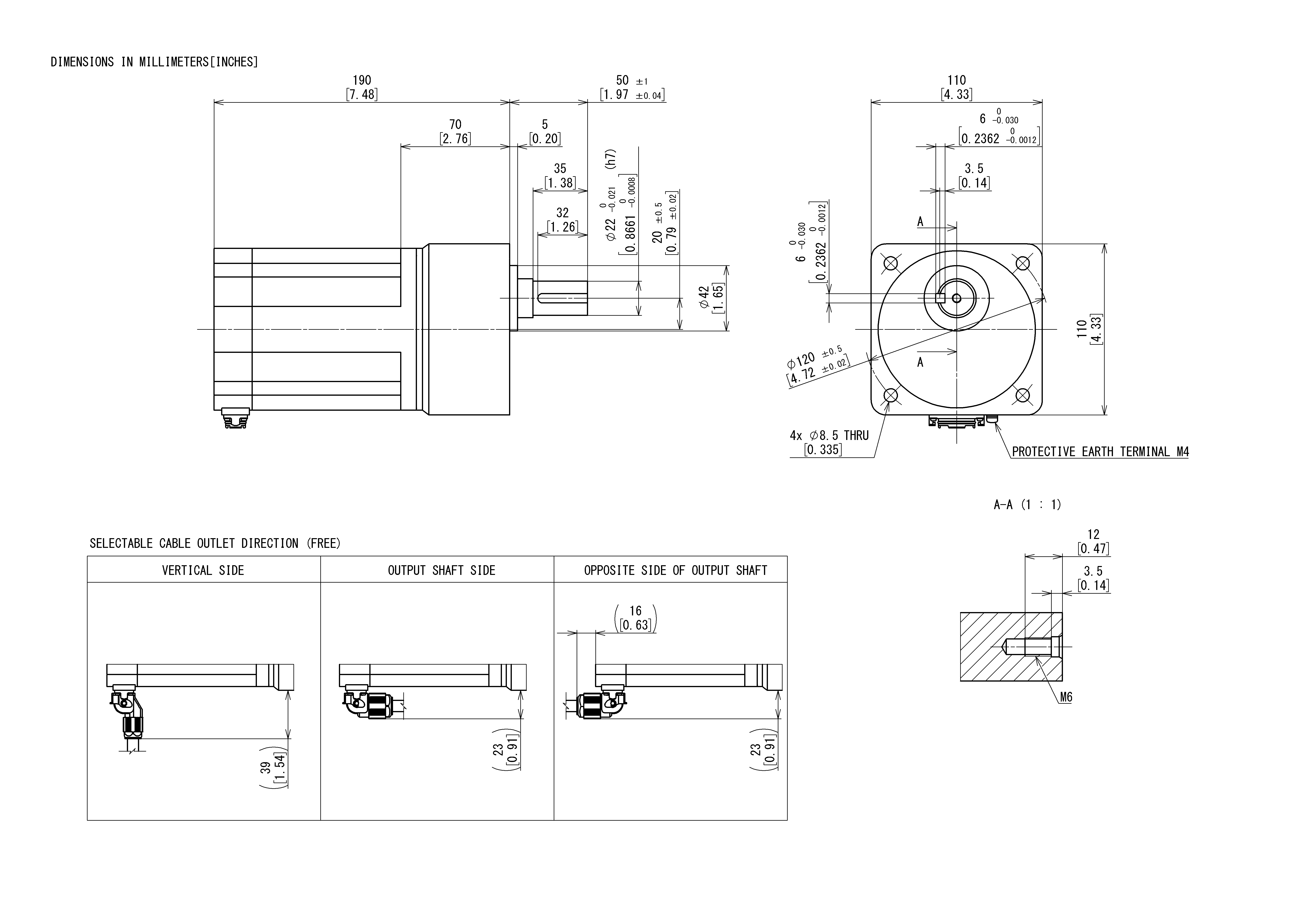
Motor/Gearhead
Data Download
Other Specifications
General Specifications
| Item | Specifications | |
|---|---|---|
| Insulation Resistance | 100 MΩ or more when a 500 VDC megger is applied between the windings and the case after continuous operation under normal ambient temperature and humidity. | |
| Dielectric Strength | Sufficient to withstand 1.5 kVAC at 50 Hz applied between the windings and the case for 1 minute after continuous operation under normal ambient temperature and humidity. | |
| Temperature Rise | After rated continuous operation under normal ambient temperature and humidity with a heat sink attached∗1, the measurement value of the temperature rise on the case surface is 40 °C max. using the thermocouple method. | |
| Operating Environment | Ambient Temperature | 0 ∼ +40 °C (Non-freezing) |
| Ambient Humidity | 85 % max. (Non-condensing) | |
| Altitude | Up to 1000 m above sea level | |
| Atmosphere | No corrosive gases or dust. Should not be exposed to water or oil. Cannot be used in a radioactive area, magnetic field, vacuum, or other special environments. | |
| Vibration | Must not be subjected to continuous vibration or excessive shock. Conforms to JIS C 60068-2-6, "Sine-Wave Vibration Test Method" Frequency Range: 10 ∼ 55 Hz, Half Amplitude: 0.15 mm, Sweep Direction: 3 directions (X, Y, Z), Number of Sweeps: 20 times |
|
| Storage Conditions∗2 | Ambient Temperature | -20 ∼ +70 °C (Non-freezing) |
| Ambient Humidity | 85 % max. (Non-condensing) | |
| Altitude | Up to 3000 m above sea level | |
| Atmosphere | No corrosive gases or dust. Should not be exposed to water or oil. Cannot be used in a radioactive area, magnetic field, vacuum, or other special environments. | |
| Thermal Class | UL/CSA Standards: 105 (A) EN Standards: 120 (E) |
|
| Degree of Protection | IP66∗3 (Excluding the mounting surface of the round shaft type) |
|
- ∗1
- The size of the heat sink (Material: Aluminum) is as follows.
350 × 350 mm, Thickness 10 mm
The round shaft type should be mounted on a heat sink to keep the motor case surface temperature 90 °C max. - ∗2
- The storage conditions apply for short periods including the transportation period.
- ∗3
- The degree of protection applies when the motor is connected to the connection cable. The driver connector part of the connection cable is excluded.
Note
- Do not measure insulation resistance or perform a dielectric strength test while the motor and driver are connected.
Permissible Radial Load and Permissible Axial Load
Parallel shaft gearhead
| Output | Gear Ratio | Permissible Radial Load | Permissible Axial Load N |
||
|---|---|---|---|---|---|
| 10 mm From the End of the Output Shaft N |
20 mm From the End of the Output Shaft N |
||||
| 30 W | 5 | At 100~3000 r/min | 100 | 150 | 40 |
| At 4000 r/min | 90 | 110 | |||
| 10, 15, 20 | At 100~3000 r/min | 150 | 200 | ||
| At 4000 r/min | 130 | 170 | |||
| 30, 50, 100, 200 | At 100~3000 r/min | 200 | 300 | ||
| At 4000 r/min | 180 | 230 | |||
| 60 W | 5 | At 100~3000 r/min | 200 | 250 | 100 |
| At 4000 r/min | 180 | 220 | |||
| 10, 15, 20 | At 100~3000 r/min | 300 | 350 | ||
| At 4000 r/min | 270 | 330 | |||
| 30, 50, 100, 200 | At 100~3000 r/min | 450 | 550 | ||
| At 4000 r/min | 420 | 500 | |||
| 120 W | 5 | At 100~3000 r/min | 300 | 400 | 150 |
| At 4000 r/min | 230 | 300 | |||
| 10, 15, 20 | At 100~3000 r/min | 400 | 500 | ||
| At 4000 r/min | 370 | 430 | |||
| 30, 50, 100, 200 | At 100~3000 r/min | 500 | 650 | ||
| At 4000 r/min | 450 | 550 | |||
| 750 W | 5, 10 | At 100~3000 r/min | 550 | 800 | 200 |
| At 4000 r/min | 500 | 700 | |||
| 15, 20, 30 | At 100~3000 r/min | 1000 | 1250 | 300 | |
| At 4000 r/min | 900 | 1100 | |||
| 50 | At 100~3000 r/min | 1300 | 1450 | 400 | |
| At 4000 r/min | 1200 | 1300 | |||
Load Position
Hollow Shaft Flat Gearhead
| Output | Gear Ratio | Permissible Radial Load | Permissible Axial Load N |
||
|---|---|---|---|---|---|
| 10 mm From Mounting Surface N |
20 mm From Mounting Surface N |
||||
| 30 W | 5, 10 | At 100~3000 r/min | 450 | 370 | 200 |
| At 4000 r/min | 410 | 330 | |||
| 15, 20, 30, 50, 100, 200 |
At 100~3000 r/min | 500 | 400 | ||
| At 4000 r/min | 460 | 370 | |||
| 60 W | 5, 10 | At 100~3000 r/min | 800 | 660 | 400 |
| At 4000 r/min | 730 | 600 | |||
| 15, 20, 30, 50, 100, 200 |
At 100~3000 r/min | 1200 | 1000 | ||
| At 4000 r/min | 1100 | 910 | |||
| 120 W | 5, 10 | At 100~3000 r/min | 900 | 770 | 500 |
| At 4000 r/min | 820 | 700 | |||
| 15, 20 | At 100~3000 r/min | 1300 | 1110 | ||
| At 4000 r/min | 1200 | 1020 | |||
| 30, 50, 100, 200 | At 100~3000 r/min | 1500 | 1280 | ||
| At 4000 r/min | 1400 | 1200 | |||
| 750 W | 5, 10 | At 100~3000 r/min | 1230 | 1070 | 800 |
| At 4000 r/min | 1130 | 990 | |||
| 15, 20 | At 100~3000 r/min | 1680 | 1470 | ||
| At 4000 r/min | 1550 | 1360 | |||
| 30, 50 | At 100~3000 r/min | 2040 | 1780 | ||
| At 4000 r/min | 1900 | 1660 | |||
Load Position
Round Shaft Type
| Output | Permissible Radial Load | Permissible Axial Load N |
|
|---|---|---|---|
| 10 mm From the End of the Output Shaft N |
20 mm From the End of the Output Shaft N |
||
| 30 W | 70 | 100 | 15 |
| 60 W | 120 | 140 | 20 |
| 120 W | 160 | 170 | 25 |
| 750 W | 262 | 304 | 25 |
Load Position
Permissible Radial Load Calculation
The formula for calculating the permissible radial load varies depending on the mechanism.
When One Side of the Load Shaft is Not Supported by the Bearing Unit
This is the mechanism in which the radial load is in the most severe condition. A Stepped Type Load Shaft is recommended.
| Product Name | Permissible Radial Load W [N] |
|---|---|
| GFS2G□FR |
\(\begin{align} \mathrm{W} [\mathrm{N}] = \frac{36}{36 + \mathrm{Lp}} \times \mathrm{F}_0 [\mathrm{N}] \end{align}\)
|
| GFS4G□FR |
\(\begin{align} \mathrm{W} [\mathrm{N}] = \frac{40}{40 + \mathrm{Lp}} \times \mathrm{F}_0 [\mathrm{N}] \end{align}\)
|
| GFS5G□FR |
\(\begin{align} \mathrm{W} [\mathrm{N}] = \frac{50}{50 + \mathrm{Lp}} \times \mathrm{F}_0 [\mathrm{N}] \end{align}\)
|
| 6GR□FRS2 |
\(\begin{align} \mathrm{W} [\mathrm{N}] = \frac{60}{60 + \mathrm{Lp}} \times \mathrm{F}_0 [\mathrm{N}] \end{align}\)
|
When One Side of the Load Shaft is Supported by the Bearing Unit
| Product Name | Permissible Radial Load W [N] |
|---|---|
| GFS2G□FR GFS4G□FR GFS5G□FR 6GR□FRS2 |
\(\begin{align} \mathrm{W} [\mathrm{N}] = \frac{\mathrm{B}}{\mathrm{B} - \mathrm{Lp}} \times \mathrm{F}_0 [\mathrm{N}] \end{align}\)
|
| Product Name | Speed | Gear Ratio | F0[N] |
|---|---|---|---|
| GFS2G□FR | At 80~3000 r/min | 5, 10 | 570 |
| 15~200 | 630 | ||
| At 4000 r/min | 5, 10 | 520 | |
| 15~200 | 580 | ||
| GFS4G□FR | At 80~3000 r/min | 5, 10 | 1000 |
| 15~200 | 1500 | ||
| At 4000 r/min | 5, 10 | 910 | |
| 15~200 | 1370 | ||
| GFS5G□FR | At 80~3000 r/min | 5, 10 | 1080 |
| 15, 20 | 1550 | ||
| 30~200 | 1800 | ||
| At 4000 r/min | 5, 10 | 980 | |
| 15, 20 | 1430 | ||
| 30~200 | 1680 | ||
| 6GR□FRS2 | At 100~3000 r/min | 5, 10 | 1430 |
| 15, 20 | 1960 | ||
| 30, 50 | 2380 | ||
| At 4000 r/min | 5, 10 | 1320 | |
| 15, 20 | 1810 | ||
| 30, 50 | 2210 |
Standards
Regulations and Standards Materials
Documents about compliance with regulations and standards can be downloaded from the "Data Download" tab on the product details page.
(The types of files available for download vary by product.)
Explanations of the Global Laws, Regulations and Standards can be found here.
Information about our compliance with safety standards for each of our product models can be found here.
Hazardous Substances
The product does not contain any substances (10 substances) exceeding the regulation values of the RoHS Directive (2011/65/EU, 2015/863/EU).
For more information about compliance with regulations on chemical substances in Oriental Motor's Products, click here.