Stepper Motors CRK Series Built-In Controller Type
CRK564RKD
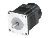
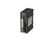
Motor/Control Circuit
| Product Classification | Product Name | List Price | Shipping Date |
|---|---|---|---|
| Motor / Control Circuit | CRK564RKD | - | Discontinued Product (31.3.2022 discontinued) |
Included
- Motor, Control Circuit, Power Supply Connector, with ConnectorCable, Lead Wires with Connector (For Motor Connection), Lead Wires with Connector (For Encoder Connection), Operating Manual
Specifications
Dimensions
Control Circuit
Data Download
Other Specifications
Driver Specifications
| Number of Positioning Data Sets | 63 Points | |
|---|---|---|
| Positioning Operation | Independent | ○ |
| Linked | ○ | |
| Linked 2 | ○ | |
| Sequential | ○ | |
| Continuous Operation | ○ | |
| JOG Operation | ○ | |
| Return-To-Home Operation | ○ | |
| Test Operation | ○ | |
| Control Module OPX-2A | ○ | |
| Support Software MEXE02 | ○ | |
RS-485 Communication Specifications
| Protocol | Modbus Protocol (Modbus RTU mode) |
|---|---|
| Electrical Characteristics | EIA-485 Compliant, Straight Cable Use twisted-pair cables (TIA/EIA-568B CAT5e or better recommended). The max. total extension length is 50 m.* |
| Mode | Half duplex communication, and asynchronous mode (Data: 8 bits, Stop bit: 1 bit or 2 bits, Parity: none, even, or odd) |
| Transmission Rate | 9600bps/19200bps/38400bps/57600bps/115200bps |
| Connection Type | Up to 31 units can be connected to a single programmable controller (master device). |
- *If a specific wiring and layout causes the motor cable or power supply cable to generate a noise problem, shield the cable or use ferrite cores.
General Specifications
| Specifications | Motor | Driver | |
|---|---|---|---|
| Thermal Class | 130 (B) | − | |
| Insulation Resistance | 100 MΩ or more when a 500 VDC megger is applied between the motor windings and the case. |
100 MΩ or more when a 500 VDC megger is applied between the following places:
|
|
| Dielectric Strength |
No abnormalities were observed even if 1.5 kV* at 50 Hz or 60 Hz is applied between the windings and the case of the motor for 1 minute.at normal temperature and humidity.
|
Sufficient to withstand the following for 1 minute:
|
|
| Operating Environment (when operating) |
Ambient Temperature |
-10~+50 °C (Non-freezing):
Standard Type, High-Resolution Type
High-torque type, TH, PS, PN geared type 0~+50 °C (Non-freezing):
PS Geared Type Φ22 mm
0~+40 °C (non-freezing):
Harmonic Geared Type
|
0~+40 °C (Non-freezing) |
| Ambient Humidity | 85 % max. (Non-condensing) | ||
| Atmosphere | No corrosive gases or dust. No exposure to water, oil or other liquids. | ||
| Temperature Rise | 5-phase excitation at rated current, winding temperature rise to 80 °C max. at standstill (resistance change method) Temperature rise of winding section at 80 °C or less (resistance change method) |
− | |
| Stop position accuracy*1 | ±3 arcmin (±0.05˚), CRK513P±10 arcmin (±0.17°) High-resolution type: ±2 arcmin (±0.034˚) |
− | |
| Shaft Runout | 0.05 T.I.R. (mm)*4 | − | |
| Radial Play*2 | 0.025 mm Max. (Load 5 N) | − | |
| Axial Play*3 | 0.075 mm Max. (Load 10 N) [CRK513P Load 1 N, CRK52□ Load 2.5 N] |
− | |
| Concentricity of Installation Pilot to the Shaft |
0.075 T.I.R. (mm)*4 | − | |
| Perpendicularity of mounting surface to the shaft |
0.075 T.I.R. (mm)*4 | − | |
- *1
- This is the value at full step and no load (Varies depending on the size of the load).
- *2
- Radial Play: Displacement in shaft position in the radial direction when a 5 N load is applied perpendicular to the tip of the motor shaft.
- *3
- Axial Play: Displacement in shaft position in the axial direction when a 10 N load (CRK513P is 1 N, CRK52□ is 2.5 N) is applied to the motor shaft in the axial direction.
- *4
- T.I.R. (Total Indicator Reading): The total dial gauge reading when the measurement section is rotated 1 revolution centered on the reference axis center.
Note
- Disconnect the motor and driver when measuring insulation resistance, or conducting a dielectric strength test.
Also, do not conduct these tests on the motor encoder section.
Rotation Direction
This indicates the rotation direction when viewed from the output shaft side.
The rotation direction of the gearhead output shaft relative to the standard type motor output shaft varies depending on the gear type and gear ratio. Please check the following table.
| Type | Gear Ratio | Rotation Direction as Viewed From the Motor Output Shaft Side |
|---|---|---|
| TS Geared Type | 3.6, 7.2, 10 | Same direction |
| 20, 30 | Opposite direction | |
| TH Geared Type Frame size 28 mm |
7.2, 10 | Opposite direction |
| 20, 30 | Same direction | |
| TH Geared Type Frame size 42 mm, 60 mm, 90 mm |
3.6, 7.2, 10 | Same direction |
| 20, 30 | Opposite direction | |
| SH Geared Type Frame size 28 mm |
7.2, 36 | Same direction |
| 9, 10, 18 | Opposite direction | |
| SH Geared Type Frame size 42 mm, 60 mm |
3.6, 7.2, 9, 10 | Same direction |
| 18, 36 | Opposite direction | |
| SH Geared Type Frame size 90 mm |
3.6, 7.2, 9, 10, 18 | Same direction |
| 36 | Opposite direction | |
| CS Geared Type | 5, 10, 15, 20 | Same direction |
|
FC Geared Type PS Geared Type PN Geared Type HPG Geared Type |
Overall gear ratio | Same direction |
| Harmonic Geared Type | 30, 50, 100 | Opposite direction |
Encoder Specifications
| Resolution | 500P/R |
|---|---|
| Output Mode | Incremental |
| Output Signals | 3 channels |
| Voltage | 5 VDC±5 % |
| Output Circuit Type | Line Driver |
Permissible Moment Load (Harmonic Geared Type)
| Motor Frame Size | Permissible Axial Load (N) | Permissible Moment Load (N·m) | Constant a (m) |
|---|---|---|---|
| 20 mm | 60 | 0.7 | 0.00485 |
| 30 mm | 140 | 2.9 | 0.0073 |
| 42 mm | 220 | 5.6 | 0.009 |
| 60 mm | 450 | 11.6 | 0.0114 |
The moment load can be calculated with the following formula.
-
Example 1: When an external force F (N) is applied to a position that extends L (m) horizontally from the center of the output flange
-
Example 2: When external force F (N) is applied to a position that extends in the vertical direction L (m) from the output flange-mounting surface.
Permissible Radial Load and Permissible Axial Load
| Type | Motor Frame Size | Motor Product Name | Gear Ratio | Permissible Radial Load | Permissible Axial Load | ||||
|---|---|---|---|---|---|---|---|---|---|
| Distance From Shaft End [mm] | |||||||||
| 0 | 5 | 10 | 15 | 20 | |||||
| High-Torque Type | 20 mm | PK213P, PK214P, PK513P | - | 12 | 15 | - | - | - | 3 |
| 28 mm | PK223P, PK224P, PK225P, PK523P, PK525P, PK523HP, PK525HP |
25 | 34 | 52 | - | - | 5 | ||
| 35 mm | PK233P, PK235P | 20 | 25 | 34 | 52 | - | 10 | ||
| 42 mm | PK244P, PK246P, PK544P, PK546P | 20 | 25 | 34 | 52 | - | 10 | ||
| 56.4 mm | PK264P, PK266P, PK268P | 61 | 73 | 90 | 110 | 160 | 20 | ||
| High-Torque and High-Efficiency Type | 42 mm | PKE243, PKE244, PKE245 | 20 | 25 | 34 | 52 | - | 10 | |
| High-Resolution Type / High-Resolution Type With Encoder |
28 mm | PK523PM, PK524PM, PK525PM, PK523HPM, PK524HPM, PK525HPM |
25 | 34 | 52 | - | - | 5 | |
| 42 mm | PK243M, PK244M, PK245M, PK544PM, PK546PM |
20 | 25 | 34 | 52 | - | 10 | ||
| 56.4 mm | PK264M, PK266M, PK268M | 54 | 67 | 89 | 130 | - | 20 | ||
| 60 mm | PK564PM, PK566PM, PK569PM | 90 | 100 | 130 | 180 | 270 | 20 | ||
| Standard Type / Standard Type Terminal Box Type / Standard Type With Encoder / Standard Type With electromagnetic brake |
42 mm | PK243, PK244, PK245, PK543 PK544, PK545 |
20 | 25 | 34 | 52 | - | 10 | |
| 50 mm | PK256, PK258 | 54 | 67 | 89 | 130 | - | 20 | ||
| 56.4 mm | PK264, PK266, PK268 | 54 | 67 | 89 | 130 | - | 20 | ||
| 60 mm | PK564, PK566, PK569 | 63 | 75 | 95 | 130 | 190 | 20 | ||
| 85 mm | PK596, PK599, PK5913, PK296 PK299, PK2913 |
260 | 290 | 340 | 390 | 480 | 60 | ||
| SH Geared Type | 28 mm | PK223P | 7.2, 9, 10, 18, 36 | 15 | 17 | 20 | 23 | - | 10 |
| 42 mm | PK243 | 3.6, 7.2, 9, 10, 18, 36, 50, 100 | 10 | 15 | 20 | 30 | - | 15 | |
| 60 mm | PK264 | 3.6, 7.2, 9, 10 | 30 | 40 | 50 | 60 | 70 | 30 | |
| 18, 36, 50, 100 | 80 | 100 | 120 | 140 | 160 | ||||
| TH Geared Type | 28 mm | PK523P | 7.2, 10, 20, 30 | 15 | 17 | 20 | 23 | - | 10 |
| 42 mm | PK543 | 3.6, 7.2, 10, 20, 30 | 10 | 14 | 20 | 30 | - | 15 | |
| 60 mm | PK564 | 70 | 80 | 100 | 120 | 150 | 40 | ||
| 90 mm | PK596 | 220 | 250 | 300 | 350 | 400 | 100 | ||
| PS Geared Type | 22 mm | PK513P | 4, 16 | 20 | 30 | - | - | - | 20 |
| 28 mm | PK523P | 5, 7.2, 10 | 45 | 60 | 80 | 100 | - | 40 | |
| 42 mm | PK545 | 5 | 70 | 80 | 95 | 120 | - | 100 | |
| 7.2 | 80 | 90 | 110 | 140 | - | ||||
| 10 | 85 | 100 | 120 | 150 | - | ||||
| PK543 | 25 | 120 | 140 | 170 | 210 | - | |||
| 36 | 130 | 160 | 190 | 240 | - | ||||
| 50 | 150 | 170 | 210 | 260 | - | ||||
| 60 mm | PK566 | 5 | 170 | 200 | 230 | 270 | 320 | 200 | |
| 7.2 | 200 | 220 | 260 | 310 | 370 | ||||
| 10 | 220 | 250 | 290 | 350 | 410 | ||||
| PK564 | 25 | 300 | 340 | 400 | 470 | 560 | |||
| 36 | 340 | 380 | 450 | 530 | 630 | ||||
| 50 | 380 | 430 | 500 | 600 | 700 | ||||
| 90 mm | PK599 | 5 | 380 | 420 | 470 | 540 | 630 | 600 | |
| 7.2 | 430 | 470 | 530 | 610 | 710 | ||||
| 10 | 480 | 530 | 590 | 680 | 790 | ||||
| PK596 | 25 | 650 | 720 | 810 | 920 | 1070 | |||
| 36 | 730 | 810 | 910 | 1040 | 1210 | ||||
| 50 | 820 | 910 | 1020 | 1160 | 1350 | ||||
| PN Geared Type | 28 mm | PK523P | 5, 7.2, 10 | 45 | 60 | 80 | 100 | − | 40 |
| 42 mm | PK544 | 5 | 80 | 95 | 120 | 160 | − | 100 | |
| 7.2 | 90 | 110 | 130 | 180 | − | ||||
| 10 | 100 | 120 | 150 | 200 | − | ||||
| 60 mm | PK566 | 5 | 240 | 260 | 280 | 300 | 330 | 200 | |
| 7.2 | 270 | 290 | 310 | 340 | 370 | ||||
| 10 | 300 | 320 | 350 | 380 | 410 | ||||
| PK564 | 25 | 410 | 440 | 470 | 520 | 560 | |||
| 36 | 360 | 410 | 480 | 570 | 640 | ||||
| 50 | 360 | 410 | 480 | 570 | 700 | ||||
| 90 mm | PK599 | 5 | 370 | 390 | 410 | 430 | 460 | 600 | |
| 7.2 | 410 | 440 | 460 | 490 | 520 | ||||
| 10 | 460 | 490 | 520 | 550 | 580 | ||||
| PK596 | 25 | 630 | 660 | 700 | 740 | 790 | |||
| 36 | 710 | 750 | 790 | 840 | 900 | ||||
| 50 | 790 | 840 | 890 | 940 | 1000 | ||||
| Harmonic Geared Type | 20 mm | PK513P | 50, 100 | 50 | 75 | - | - | - | 60 |
| 30 mm | PK523HP | 110 | 135 | 175 | 250 | - | 140 | ||
| 42 mm | PK543 | 180 | 220 | 270 | 360 | 510 | 220 | ||
| 60 mm | PK564 | 320 | 370 | 440 | 550 | 720 | 450 | ||
| 90 mm | PK596 | 1090 | 1150 | 1230 | 1310 | 1410 | 1300 | ||
- The product names are listed such that the product names are distinguishable.
- PS, PN Geared Type: Standard Input Rotation Speed: 1500 r/m, the value satisfies a calculated lifetime of 20,000 hours when either the permissible radial load or the permissible axial load are applied.
Radial Load and Axial Load
Standards
Regulations and Standards Materials
Documents about compliance with regulations and standards can be downloaded from the "Data Download" tab on the product details page.
(The types of files available for download vary by product.)
Explanations of the Global Laws, Regulations and Standards can be found here.
Information about our compliance with regulations and standards for each of our product series can be found here.
Hazardous Substances
The product does not contain any substances (10 substances) exceeding the regulation values of the RoHS Directive (2011/65/EU, 2015/863/EU).
For more information about compliance with regulations on chemical substances in Oriental Motor's Products, click here.
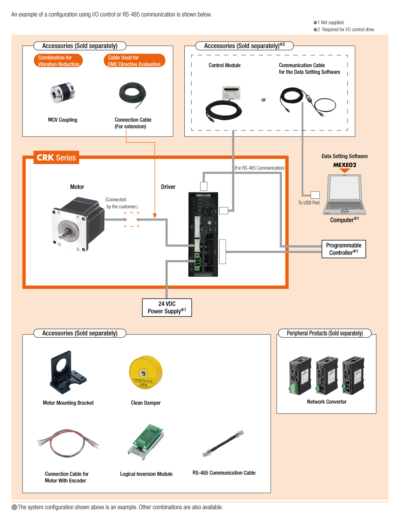
System Configuration
Related Products
Network Converter
| Products | Features | ||
|---|---|---|---|
NETC02-CC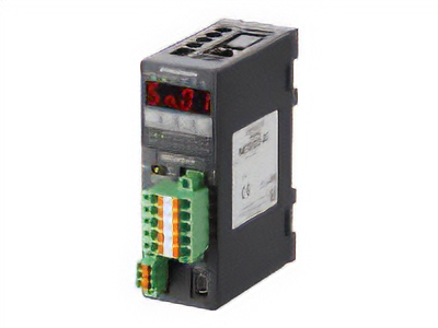
|
Features |
[CC-Link Ver. 2 Compatible] By supporting CC-Link Ver.2, you can simplify the ladder program and shorten the communication time for data sending and receiving. |
|
| Products |
NETC01-ECT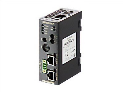
|
Features |
[EtherCAT Compatible] |