Reversible Motors KII Series (New standard)
5RK60A-UCT2
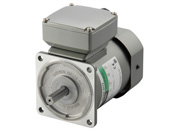
Motor
This product is currently no longer available for sale.
| Product Classification | Product Name | List Price | Shipping Date |
|---|---|---|---|
| Motor | 5RK60A-UCT2 | - | Discontinued Product (31.3.2024 discontinued) |
Included
- Motor, Capacitor, Capacitor Cap, Operating Manual
Specifications
Dimensions
Motor

Capacitor
Data Download
Other Specifications
General Specifications
| Item | Specifications |
|---|---|
| Insulation Resistance | 100 MΩ or more when a 500 VDC megger is applied between the windings and the case after 30 minutes continuous operation under normal ambient temperature and humidity. |
| Dielectric Strength | Sufficient to withstand 1.5 kVAC at 50 Hz or 60 Hz applied between the motor windings and the case for 1 minute after 30 minutes continuous operation under normal ambient temperature and humidity. |
| Temperature Rise | After 30 minutes of continuous operation at normal ambient temperature and humidity with the gearhead or equivalent heat sink* connected to the motor, the winding temperature rise value measured using the resistance change method will be 80 °C max. |
| Thermal Class | 130 (B) |
| Overheat Protective Device | The 6 W type is impedance protected Other types: Built-in thermal protector (Automatic return type) Open: 130 ± 5 °C, Return: 85 ± 20 °C |
| Operating Ambient Temperature | Single-Phase 100 VAC, Single-Phase 200 VAC: -10~+50 °C (Non-freezing) Other voltages: -10~+40 °C (Non-freezing) For gearhead gear ratios 2 or 3 the lower temperature limit is 0 °C. |
| Operating Ambient Humidity | 85 % max. (Non-condensing) |
| Degree of Protection |
Terminal box type:
IP40 (25 W, 40 W)
IP20 (60 W, 90 W) Lead wire type:
IP20
|
- * Heat Sink Size (Material: Aluminum)
| Motor Type (Output power) | Size (mm) | Thickness (mm) |
|---|---|---|
| 6 W Type | 115 x 115 | 5 |
| 15 W Type | 125 x 125 | |
| 25 W Type | 135 x 135 | |
| 40 W Type | 165 x 165 | |
| 60 W, 90 W Type | 200 x 200 |
Permissible Radial Load and Permissible Axial Load of Round Shaft
| Product Name | Permissible Radial Load N | Permissible Axial Load | |
|---|---|---|---|
| Distance From the End of the Motor Output Shaft | |||
| 10 mm | 20 mm | ||
| 2IK6 2RK6 |
50 | 110 | Half of the motor mass or less* |
| 3IK15 3RK15 |
40 | 60 | |
| 4IK25 4RK25 |
90 | 140 | |
| 5IK40 5RK40 |
140 | 200 | |
| 5IK60 5IK90 5RK60 5RK90 |
240 | 270 | |
- * Avoid applying axial loads as much as possible.
If an axial load is unavoidable, keep it at half or less of the motor mass.
System Configuration
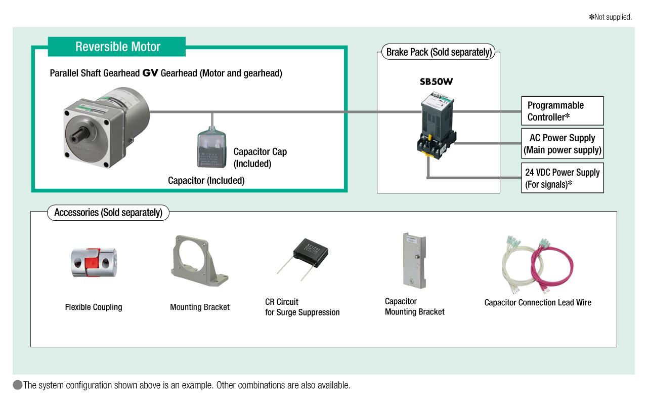
Cables and Accessories
close