Q.The stepper motor is trying to move, but it is working strangely (stalling, noise and vibration, position deviation). What are the possible causes?
Confirm the cause behind the stepper motor stalling.
-
Try to ease the operation conditions
If operation conditions (acceleration/deceleration rate, pulse frequency, etc.) are severe, the stepper motor may stall.
Confirm whether stalling can be eliminated by easing the operation condition.Refer to the following technical reference page for acceleration/deceleration rates.
See here for acceleration/deceleration rate reference valuesThe starting speed should be set at the self-starting frequency (fs) max. of the motor.
The self-starting frequency can be confirmed on the rotation speed-torque characteristics diagram* of the product. -
Confirm the mechanism conditions
If the load or inertia is too large, stalling may occur due to insufficient torque.
Confirm that the mechanism load does not exceed the stepper motor capacity.Refer to the following technical reference page for permissible values of inertia.
See here for permissible values of inertia (reference values)The load applied to the motor (required torque) should be less than the pullout torque of the motor.
The pullout torque can be confirmed on the rotation speed-torque characteristics diagram* of the product.
Oriental Motors recommends that you consider safety factor when selecting a motor. -
Confirm that the motor wire is wired correctly
If wired incorrectly, it may make noise or vibrate. Confirm that the motor wire is wired correctly. -
Confirm if the motor wire is broken
If the motor wire is broken, the stepper motor will stall. Confirm the motor wire for disconnection.
- *The rotation speed-torque characteristics diagram is available on the product details page. (Click here to see how to search for product names)
-
How to confirm for wiring errors and broken wires
-
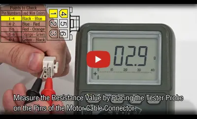
Set the measurement range of the digital circuit tester to resistance [Ω].
(Do not use an analog circuit tester, as it may not be able to measure the resistance value.) - Short-Circuit the circuit tester pin and confirm that it displays 0 Ω.
- Measure the resistance value of each lead wire (between terminals) with a circuit tester.
- Example using the 5-phase stepper motor and driver package RKII Series
Watch the video to see the features.
- *The combination of terminals to be measured and the resistance value between terminals differ by model
-
Determine the current state based on measured resistance values.
Measurement Results Diagnosis The resistance value between terminals is the same resistance value. Normal The resistance value between terminals that are wired incorrectly is about 1.5 times higher compared to those that are wired correctly. Wiring Error The resistance value will be clearly different from the normal resistance value between the terminals. Disconnection
-
Set the measurement range of the digital circuit tester to resistance [Ω].
Product Category: αSTEP, Stepper Motor
Model and Series: General
Description: Abnormalities and troubles
FAQ No.: 237
Related FAQs
Email to Technical Support
After opening the email, we will check the contents and contact you. Please note that depending on the nature of your enquiry, we may contact you by phone.