Stepper Motors RKII Series
RKS544RCD
Motor/Control Circuit
| Product Classification | Product Name | List Price | Shipping Date |
|---|---|---|---|
| Motor / Control Circuit | RKS544RCD | - | Discontinued Product (1.4.2015 discontinued) |
Included
- Motor, Control Circuit, Connector for Power Input Terminal, Connector for Main Power Input Terminal, Sensor Signal Connector, Input Signal Connector, Output Signal Connector
Specifications
Data Download
Other Specifications
Driver Specifications
| Built-in Controller Type | Pulse input type | |
|---|---|---|
| Maximum Input Pulse Frequency | − |
Line driver output by host controller: 500 kHz (at 50 % duty) Open-Collector Output by Host Controller: 250 kHz (at 50 % duty) Negative logic pulse input |
| Input Signals | Photocoupler Input, Input Signal Voltage: 11.4 V~26.4 V |
Photocoupler Input, Input Signal Voltage: 11.4 V~26.4 V (AWO, CS, FREE, ALM-RST) Photocoupler Input, Input Signal Voltage: 3 V~5.25 V (CW (PLS) +5 V, CCW (DIR) +5 V) Photocoupler Input, Input Signal Voltage: 21.6 V~26.4 V (CW (PLS) +24 V, CCW (DIR) +24 V) |
| Output Signals |
Photocoupler and Open-Collector Output External operating conditions: 30VDC 10 mA max. |
Photocoupler and Open-Collector Output External operating conditions: 30VDC 10 mA max. (READY, ALM, TIM) |
| Number of Positioning Data Sets | 64 Points | − |
| Positioning Operation | Independent, linked, linked 2, sequential, direct | − |
| Other operations | Continuous operation, JOG operation, return-to-home operation, Test Operation |
− |
| Control Module OPX-2A |
O | − |
| Support Software MEXE02 |
O | − |
General Specifications
| Motor | Driver | |||
|---|---|---|---|---|
| Built-in Controller Type | Pulse input type | |||
| Thermal Class | 130 (B) [UL is 105 (A) certified] |
− | ||
| Insulation Resistance |
100 MΩ or more when a 500 VDC megger is applied between the following places.
|
100 MΩ or more when a 500 VDC megger is applied between the following places.
|
||
| Dielectric Strength |
Sufficient to withstand the following for 1 minute:
|
Sufficient to withstand the following for 1 minute: | ||
|
|
|||
| Operating Environment (when operating) |
Ambient Temperature |
-10~+50 °C (Non-freezing): Standard Type TS/PS/FC geared type 0~+50 °C (Non-freezing): With encoder 0~+40 °C (Non-freezing): Harmonic Geared Type According to Oriental Motor’s measurement conditions |
0~+55 °C*2 (Non-freezing) | |
| Ambient Humidity | 85 % max. (Non-condensing) | |||
| Atmosphere | No corrosive gases or dust. No exposure to water, oil or other liquids. | |||
| Temperature Rise | 5-phase excitation at rated current, 80 °C max. at standstill Temperature rise of winding section at 80 °C or less (resistance change method) |
− | ||
| Degree of Protection | IP20 | IP10 | IP20 | |
| Stop position accuracy*3 | ±3 arc minute (±0.05˚) | |||
| Shaft Runout | 0.05 T.I.R. (mm)*4 | − | ||
| Radial Play*5 | 0.025 mm Max. (Load 5 N) | − | ||
| Axial Play*6 | 0.075 mm Max. (Load 10 N) | − | ||
| Concentricity of Installation Pilot to the Shaft |
0.075 T.I.R. (mm)*4 | − | ||
| Perpendicularity of mounting surface to the shaft |
0.075 T.I.R. (mm)*4 | − | ||
- *1
- (Only for types with electromagnetic brake)
- *2
- When a heat sink of a capacity at least equivalent to an aluminum plate with a size of 200×200 mm and 2 mm thickness
- *3
- 0.72˚ is the value under no load. (The value changes with the size of the load.)
- *4
- T.I.R. (Total Indicator Reading): The total dial gauge reading when the measurement section is rotated 1 revolution centered on the reference axis center.
- *5
- Radial Play: Displacement in shaft position in the radial direction when a 5 N load is applied perpendicular to the tip of the motor shaft.
- *6
- Axial Play: Displacement in shaft position in the axial direction when a 10 N load is applied to the motor shaft in the axial direction.
Note
- Disconnect the motor and driver when measuring insulation resistance, or conducting a dielectric strength test.
Permissible Radial Load and Permissible Axial Load
| Type | Motor Frame Size | Type | Gear Ratio | Permissible Radial Load | Permissible Axial Load | ||||
|---|---|---|---|---|---|---|---|---|---|
| Distance From Shaft End [mm] | |||||||||
| 0 | 5 | 10 | 15 | 20 | |||||
| Standard Type With Encoder |
42 mm | RKS543 | − | 35 | 44 | 58 | 85 | − | 3.1 |
| RKS544 | 3.7 | ||||||||
| RKS545 | 4.3 | ||||||||
| 60 mm | RKS564 | 90 | 100 | 130 | 180 | 270 | 7.8 | ||
| RKS566 | 9.8 | ||||||||
| RKS569 | 14.7 | ||||||||
| 85 mm | RKS596 | 260 | 290 | 340 | 390 | 480 | 19.6 | ||
| RKS599 | 30.4 | ||||||||
| RKS5913 | 41.2 | ||||||||
Rotation Direction
This indicates the rotation direction when viewed from the output shaft side.
The rotation direction of the gearhead output shaft relative to the standard type motor output shaft varies depending on the gear type and gear ratio. Please check the following table.
| Type | Gear Ratio | Rotation Direction as Viewed From the Motor Output Shaft Side |
|---|---|---|
| TS Geared Type | 3.6, 7.2, 10 | Same direction |
| 20, 30 | Opposite direction | |
| TH Geared Type Frame size 28 mm |
7.2, 10 | Opposite direction |
| 20, 30 | Same direction | |
| TH Geared Type Frame size 42 mm, 60 mm, 90 mm |
3.6, 7.2, 10 | Same direction |
| 20, 30 | Opposite direction | |
| SH Geared Type Frame size 28 mm |
7.2, 36 | Same direction |
| 9, 10, 18 | Opposite direction | |
| SH Geared Type Frame size 42 mm, 60 mm |
3.6, 7.2, 9, 10 | Same direction |
| 18, 36 | Opposite direction | |
| SH Geared Type Frame size 90 mm |
3.6, 7.2, 9, 10, 18 | Same direction |
| 36 | Opposite direction | |
| CS Geared Type | 5, 10, 15, 20 | Same direction |
|
FC Geared Type PS Geared Type PN Geared Type HPG Geared Type |
Overall gear ratio | Same direction |
| Harmonic Geared Type | 30, 50, 100 | Opposite direction |
RS-485 Communication Specifications
| Protocol | Modbus RTU Mode |
|---|---|
| Electrical Characteristics | EIA-485 Compliant, Straight Cable Use twisted-pair cables (TIA/EIA-568B CAT5e or better recommended). The max. total extension length is 50 m.* |
| Mode | Half duplex and asynchronous mode (data: 8 bits, stop bit: 1 bit or 2 bits, parity: none, even, or odd) |
| Transmission Rate | 9600bps/19200bps/38400bps/57600bps/115200bps |
| Connection Type | A maximum of 31 units can be connected to a single host connection device. |
- *If a specific wiring and layout causes the motor cable or power supply cable to generate a noise problem, shield the cable or use ferrite cores.
Encoder Specifications
| Resolution | 500P/R |
|---|---|
| Output Mode | Incremental |
| Output Signals | 3 channels |
| Output Circuit Type | Line Driver |
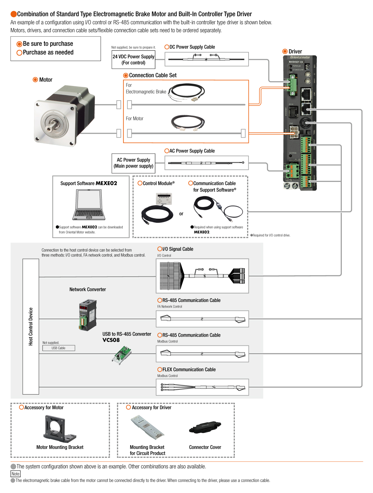
System Configuration
Related Products
Network Converter
| Products | Features | ||
|---|---|---|---|
NETC02-CC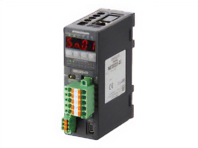
|
Features |
[CC-Link Ver. 2 Compatible] By supporting CC-Link Ver.2, you can simplify the ladder program and shorten the communication time for data sending and receiving. |
|
| Products |
NETC01-ECT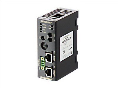
|
Features |
[EtherCAT Compatible] |