Brushless Motors HBL Series
HBL560N-100
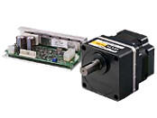
Gearhead / Motor / Control Circuit
This product is currently no longer available for sale.
| Product Classification | Product Name | List Price | Shipping Date |
|---|---|---|---|
| Gearhead / Motor / Control Circuit | HBL560N-100 | - | Discontinued Product (1.4.2014 discontinued) |
Included
- Motor, Control Circuit, I/O Signals Cable with Connectors, With ConnectorPower Supply Cable, Mounting Screw Set, Operating Manual
Specifications
Other Specifications
Common Specifications
| Item | Specifications |
|---|---|
| Speed Setting Methods |
Set 1 method from the following.
|
| Multi-Speed Setting Methods | 2-Speed 1-Speed by Internal Speed Potentiometer (1 pc) and 1-Speed by External Speed Potentiometer (accessory PAVR-20KZ) or external DC voltage (0-5VDC) |
| Input Signals | C-MOS Negative Logic Input Method Operated by Internal Power Supply Common to start/stop input, run/brake input, rotation direction switching input, and speed setting mode selection input |
| Output Signals | Open-collector output Operated by external power supply Operating conditions 26.4 VDC 10 mA max. Common to alarm output and speed output |
| Protective Functions* | When the following protective functions are activated, an alarm signal will be output, and the motor will come to a stop.
|
| Maximum Extension Distance | Motor and driver distance: 5 m (when an accessory connection cable is used) |
| Time Rating | Continuous |
- *The HBL series cannot control the speed control of the motor in applications where the motor side is turned from the load side, such as gravitational operation.
When a load exceeding the permissible load inertia value is driven, or when gravitational operation is performed, the overvoltage protective function works to bring the motor to a coasting stop.
General Specifications
| Item | Motor | Driver | |
|---|---|---|---|
| Insulation Resistance | 100 MΩ or more when a 500 VDC megger is applied between the windings and the case after continuous operation under normal ambient temperature and humidity. | After continuous operation at normal ambient temperature and humidity, the value measured with a 500 VDC megger between the power supply input and the heat sink is min. 100 MΩ. | |
| Dielectric Strength | No abnormality is observed even with an application of 0.5 kVAC at 50 Hz between the coils and the case for 1 minute after continuous operation at normal ambient temperature and humidity. | After continuous operation at normal ambient temperature and humidity, no abnormality is observed when 50 Hz, 0.5 kVAC is applied between the power supply input and the heat sink for 1 minute. | |
| Operating Environment | Ambient Temperature | 0∼+50°C (Non-freezing) | |
| Ambient Humidity | 85% maximum (Non-condensing) | ||
| Atmosphere | No corrosive gases or dust | ||
| Thermal Class | 120 (E) | − | |
Permissible Radial Load and Permissible Axial Load
Gearhead
| Product Name | Gear Ratio | Permissible Radial Load N | Permissible Axial Load N |
|
|---|---|---|---|---|
| 10 mm From Shaft End | 20 mm From Shaft End | |||
| HBL560N-□ HBL5100N-□ |
5 | 300 | 400 | 150 |
| 10, 15, 20 | 400 | 500 | ||
| 30, 50, 100, 200 | 500 | 650 | ||
Round Shaft Type
| Product Name | Permissible Radial Load N | Permissible Axial Load | |
|---|---|---|---|
| 10 mm From Shaft End | 20 mm From Shaft End | ||
| HBL560N-A | 130 | 150 | Half of the motor mass or less |
| HBL5100N-A | 160 | 170 | |
Cables and Accessories
close