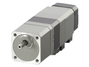
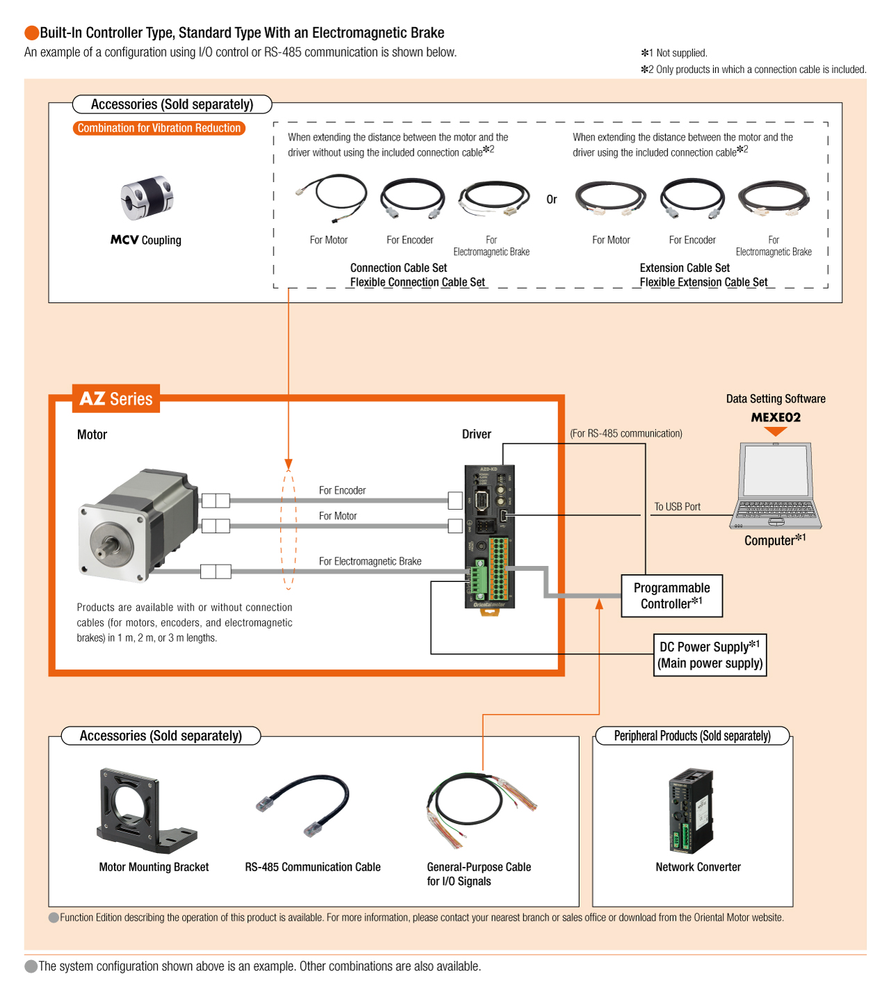
αSTEP Battery-Free Built-In Absolute Encoder AZ Series
AZ46MKD-TS10-3
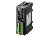
Motor/Control Circuit
| Product Classification | Product Name | List Price | Shipping Date |
|---|---|---|---|
| Geared Motor / Control Circuit | AZ46MKD-TS10-3 | - | Discontinued Product (31.3.2020 discontinued) |
Included
- Motor, Control Circuit, Motor Connection Cable (3 m), Encoder Connection Cable (3 m), Cable for Electromagnetic Brake (3 m), Main Power Supply/Electromagnetic Brake Connector (CN1), I/O Signal Connector (CN4), Operating Manual
Specifications
Dimensions
Data Download
Other Specifications
Driver Specifications
| Driver Product Name | AZD-KD | AZD-KX AZD-K |
AZD-KEP2, AZD-KEP AZD-KED2, AZD-KED AZD-KPN2, AZD-KPN |
|
|---|---|---|---|---|
| Interface | Pulse Input | - |
|
|
| Control Input | 10 Points Photocoupler |
6 Points Photocoupler |
6 Points Photocoupler |
|
| Pulse output | 2 Points Line Driver |
2 Points Line Driver |
2 Points Line Driver |
|
| Control output | 6 Points Photocoupler and Open-Collector |
6 Points Photocoupler and Open-Collector |
6 Points Photocoupler and Open-Collector |
|
| Power Shut Down Input Signals | - | - | 2 Points Photocoupler |
|
| Power Shut Down Monitor Output | - | - | 1 Point Photocoupler and Open-Collector |
|
Driver function
| Built-In Controller Type | Pulse Input Type with RS-485 Communication | Pulse Input Type |
EtherNet/IP Compatible PROFINET Compatible |
||||
|---|---|---|---|---|---|---|---|
| Number of Positioning Data Sets | 256 Points | 256 Points*1 | 256 Points | ||||
| Remote I/O | Input | 16 Points | - | 16 Points | |||
| Output | 16 Points | - | 16 Points | ||||
| Setting Tool | Support Software MEXE02 | ||||||
| Coordinates Management Method | Battery-free Absolute System | ||||||
| Operation | Positioning Operation | Product Line | Positioning Operation | ○ | ○ | ○*1 | ○ |
| Positioning Push-Motion Operation*2 |
○ | ○ | ○*1 | ○ | |||
| Fastening method | Single-motion Operation | ○ | ○ | ○*1 | ○ | ||
| Sequential Operation | ○ | ○ | ○*1 | ○ | |||
| Multistep Speed-Change (Configuration connection) |
○ | ○ | ○*1 | ○ | |||
| Sequence control | Loop Operation (Repeating) |
○ | ○ | ○*1 | ○ | ||
| Event Jump Operation | ○ | ○ | ○*1 | ○ | |||
| Speed Control Operation (Continuous operation) | ○ | ○ | ○*1 | ○ | |||
| Return-To-Home Operation | Return-To-Home Operation | ○ | ○ | ○ | ○ | ||
| High-speed return-to-home operation | ○ | ○ | ○ | ○ | |||
| JOG Operation | ○ | ○ | ○ | ○ | |||
| Monitor/Information | Waveform Monitoring | ○ | ○ | ○ | ○ | ||
| Overload Detection | ○ | ○ | ○ | ○ | |||
| Overheat Detection (Motor and Driver) |
○ | ○ | ○ | ○ | |||
| Position/Speed Information | ○ | ○ | ○ | ○ | |||
| Temperature Detection (Motor and Driver) |
○ | ○ | ○ | ○ | |||
| Motor Load Factor | ○ | ○ | ○ | ○ | |||
| Travel Distance , Cumulative Travel Distance | ○ | ○ | ○ | ○ | |||
| Alarm | ○ | ○ | ○ | ○ | |||
- *1
- It can be used by setting it with the MEXE02 support software.
- *2
- Push-motion operation is not available for the geared motor and electric actuator DGII Series.
RS-485 Communication Specifications
| Protocol | Modbus RTU Mode |
|---|---|
| Electrical Characteristics | EIA-485 Compliant, Straight Cable Use twisted-pair cables (TIA/EIA-568B CAT5e or better recommended). The max. total extension length is 50 m.* |
| Mode | Half duplex communication and asynchronous mode (data: 8 bits, stop bit: 1 bit or 2 bits, parity: none, even, or odd) |
| Transmission Rate | 9600 bps, 19200 bps, 38400 bps, 57600 bps, 115200 bps, and 230400 bps are available. |
| Connection Type | Up to 31 units can be connected to a single programmable controller (master device). |
- *If a specific wiring and layout causes the motor cable or power supply cable to generate a noise problem, shield the cable or use ferrite cores.
General Specifications
| Motor | Driver | ||
|---|---|---|---|
| Thermal Class | 130(B) [UL/CSA Standards acquisition is certified at 105 (A).] |
− | |
| Insulation Resistance | 100 MΩ or more when a 500 VDC megger is applied between the following places.
|
100 MΩ or more when a 500 VDC megger is applied between the following places.
|
|
| Dielectric Strength |
Sufficient to withstand the following for 1 minute: AZM14, AZM15, AZM24, AZM26
AZM46, AZM48, AZM66, AZM69
|
− | |
| Operating Environment (when operating) |
Ambient Temperature | 0~+40 °C (Non-freezing) | 0~+50 °C (Non-freezing) |
| Ambient Humidity | 85 % max. (Non-condensing) | ||
| Atmosphere | Cable type: No corrosive gases or dust. No exposure to water, oil or other liquids. Connector type: No corrosive gases or dust. No exposure to oil or other liquids. |
No corrosive gases or dust. No exposure to water, oil or other liquids. | |
| Degree of Protection |
Cable type (except for mounting surface and connector part): Connector type (when the connection cable is connected. |
IP10 | |
| Stop Position Accuracy |
AZM14, AZM15, AZM24, AZM26: ±5 arcmin (±0.083˚) AZM46, AZM48: ±4 arcmin (±0.067˚) AZM66, AZM69: ±3 arcmin (±0.05˚) |
||
| Shaft Runout | 0.05 T.I.R. (mm)*3 | − | |
| Concentricity of Installation Pilot to the Shaft |
0.075 T.I.R. (mm)*3 | − | |
| Perpendicularity of Mounting Surface to the Shaft |
0.075 T.I.R. (mm)*3 | − | |
| Multi-Rotation Detection Range in Power OFF State |
AZM14, AZM15, AZM24, AZM26: ±450 rotations (900 rotations) AZM46, AZM48, AZM66, AZM69: ±900 rotations (1800 rotations) |
||
- *1
- (Only for types with electromagnetic brake)
- *2
- When the motor cable shape is horizontal pull-out
- *3
- T.I.R. (Total Indicator Reading): The total dial gauge reading when the measurement section is rotated once centered on the reference axis center.
Note
- Disconnect the motor and driver when measuring insulation resistance, or conducting a dielectric strength test.
Also, do not conduct these tests on the ABZO sensor part of the motor.
Permissible Radial Load and Permissible Axial Load
| Type | Motor Frame Size Dimension |
Motor Product Name |
Gear Ratio | Permissible Radial Load | Permissible Axial Load |
||||
|---|---|---|---|---|---|---|---|---|---|
| Distance From Shaft End [mm] | |||||||||
| 0 | 5 | 10 | 15 | 20 | |||||
| Standard Type | 20 mm | AZM14 AZM15 AZME14 |
- | 12 | 15 | - | - | - | 3 |
| 28 mm | AZM24 AZM26 AZME24 |
25 | 34 | 52 | - | - | 5 | ||
| 42 mm | AZM46 | 35 | 44 | 58 | 85 | - | 15 | ||
| AZM48 | 30 | 35 | 44 | 58 | 85 | ||||
| 60 mm | AZM66 AZM69 |
90 | 100 | 130 | 180 | 270 | 30 | ||
| 85 mm | AZM98 AZM911 |
260 | 290 | 340 | 390 | 480 | 60 | ||
| TS Geared Type | 42 mm | AZM46 | 3.6, 7.2, 10 | 20 | 30 | 40 | 50 | - | 15 |
| 20, 30 | 40 | 50 | 60 | 70 | - | ||||
| 60 mm | AZM66 | 3.6, 7.2, 10 | 120 | 135 | 150 | 165 | 180 | 40 | |
| 20, 30 | 170 | 185 | 200 | 215 | 230 | ||||
| 90 mm | AZM98 | 3.6, 7.2, 10 | 300 | 325 | 350 | 375 | 400 | 150 | |
| 20, 30 | 400 | 450 | 500 | 550 | 600 | ||||
| PS geared type | 28 mm | AZM24 | 7.2, 10 | 45 | 60 | 80 | 100 | - | 40 |
| 42 mm | AZM46 | 5 | 70 | 80 | 95 | 120 | - | 100 | |
| 7.2 | 80 | 90 | 110 | 140 | - | ||||
| 10 | 85 | 100 | 120 | 150 | - | ||||
| 25 | 120 | 140 | 170 | 210 | - | ||||
| 36 | 130 | 160 | 190 | 240 | - | ||||
| 50 | 150 | 170 | 210 | 260 | - | ||||
| 60 mm | AZM66 | 5 | 170 | 200 | 230 | 270 | 320 | 200 | |
| 7.2 | 200 | 220 | 260 | 310 | 370 | ||||
| 10 | 220 | 250 | 290 | 350 | 410 | ||||
| 25 | 300 | 340 | 400 | 470 | 560 | ||||
| 36 | 340 | 380 | 450 | 530 | 630 | ||||
| 50 | 380 | 430 | 500 | 600 | 700 | ||||
| 90 mm | AZM98 | 5 | 380 | 420 | 470 | 540 | 630 | 600 | |
| 7.2 | 430 | 470 | 530 | 610 | 710 | ||||
| 10 | 480 | 530 | 590 | 680 | 790 | ||||
| 25 | 650 | 720 | 810 | 920 | 1070 | ||||
| 36 | 730 | 810 | 910 | 1040 | 1210 | ||||
| 50 | 820 | 910 | 1020 | 1160 | 1350 | ||||
| PN Geared Type | 28mm | AZM24 | 10 | 45 | 60 | 80 | 100 | - | 40 |
| 42mm | AZM46 | 5 | 80 | 95 | 120 | 160 | - | 100 | |
| 7.2 | 90 | 110 | 130 | 180 | - | ||||
| 10 | 100 | 120 | 150 | 200 | - | ||||
| 60mm | AZM66 | 5 | 240 | 260 | 280 | 300 | 330 | 200 | |
| 7.2 | 270 | 290 | 310 | 340 | 370 | ||||
| 10 | 300 | 320 | 350 | 380 | 410 | ||||
| 90mm | AZM98 | 5 | 370 | 390 | 410 | 430 | 460 | 600 | |
| 7.2 | 410 | 440 | 460 | 490 | 520 | ||||
| 10 | 460 | 490 | 520 | 550 | 580 | ||||
| HPG Geared Type | 40 mm | AZM46 | 5 | 150 | 170 | 190 | 230 | 270 | 430 |
| 9 | 180 | 200 | 230 | 270 | 320 | 510 | |||
| 60 mm | AZM66 | 5 | 250 | 270 | 300 | 330 | 360 | 700 | |
| 15 | 360 | 380 | 420 | 460 | 510 | 980 | |||
| 90 mm | AZM98 | 5 | 600 | 630 | 670 | 710 | 750 | 1460 | |
| 15 | 830 | 880 | 930 | 980 | 1050 | 2030 | |||
| Harmonic Geared Type |
30 mm | AZM24 | 50, 100 | 100 | 135 | 175 | 250 | - | 140 |
| 42 mm | AZM46 | 180 | 220 | 270 | 360 | 510 | 220 | ||
| 60 mm | AZM66 | 320 | 370 | 440 | 550 | 720 | 450 | ||
| 90 mm | AZM98 | 1090 | 1150 | 1230 | 1310 | 1410 | 1300 | ||
| FC Geared Type | 35 mm | AZM24 | 7.2, 15, 25 | 80 | 120 | 180 | 230 | - | 80 |
| 42 mm | AZM46 | 7.2, 10, 20, 30 | 180 | 200 | 220 | 250 | - | 100 | |
| 60 mm | AZM66 | 270 | 290 | 310 | 330 | 350 | 200 | ||
- The product names are listed such that the product names are distinguishable.
- PS,PN, HPG Geared Type: When either the radial load or the axial load is applied, the permissible value is set as a value that satisfies the life of 20,000 hours.
Radial Load and Axial Load
Standards
Regulations and Standards Materials
Documents about compliance with regulations and standards can be downloaded from the "Data Download" tab on the product details page.
(The types of files available for download vary by product.)
Explanations of the Global Laws, Regulations and Standards can be found here.
Information about our compliance with regulations and standards for each of our product series can be found here.
Hazardous Substances
The product does not contain any substances (10 substances) exceeding the regulation values of the RoHS Directive (2011/65/EU, 2015/863/EU).
For more information about compliance with regulations on chemical substances in Oriental Motor's Products, click here.
System Configuration
Related Products
Network Converter
| Products | Features | ||
|---|---|---|---|
NETC02-CC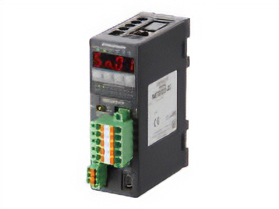
|
Features |
[CC-Link Ver. 2 Compatible] By supporting CC-Link Ver.2, you can simplify the ladder program and shorten the communication time for data sending and receiving. |
|
| Products |
NETC01-ECT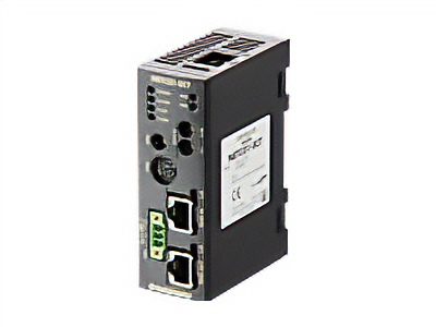
|
Features |
[EtherCAT Compatible] |
Cables and Accessories