Reversible Motors KII Series (New standard)
5RK90A-GCT2
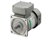
Motor
This product is currently no longer available for sale.
| Product Classification | Product Name | List Price | Shipping Date |
|---|---|---|---|
| Motor | 5RK90A-GCT2 | - | Discontinued Product (31.3.2024 discontinued) |
Included
- Motor, Capacitor, Capacitor Cap, Operating Manual
Specifications
Data Download
Other Specifications
General Specifications
| Item | Specifications |
|---|---|
| Insulation Resistance | 100 MΩ or more when a 500 VDC megger is applied between the windings and the case after 30 minutes continuous operation under normal ambient temperature and humidity. |
| Dielectric Strength | Sufficient to withstand 1.5 kVAC at 50 Hz or 60 Hz applied between the motor windings and the case for 1 minute after 30 minutes continuous operation under normal ambient temperature and humidity. |
| Temperature Rise | After 30 minutes of continuous operation at normal ambient temperature and humidity with the gearhead or equivalent heat sink* connected to the motor, the winding temperature rise value measured using the resistance change method will be 80 °C max. |
| Thermal Class | 130 (B) |
| Overheat Protective Device | The 6 W type is impedance protected Other types: Built-in thermal protector (Automatic return type) Open: 130 ± 5 °C, Return: 85 ± 20 °C |
| Operating Ambient Temperature | Single-Phase 100 VAC, Single-Phase 200 VAC: -10~+50 °C (Non-freezing) Other voltages: -10~+40 °C (Non-freezing) For gearhead gear ratios 2 or 3 the lower temperature limit is 0 °C. |
| Operating Ambient Humidity | 85 % max. (Non-condensing) |
| Degree of Protection |
Terminal box type:
IP40 (25 W, 40 W)
IP20 (60 W, 90 W) Lead wire type:
IP20
|
- * Heat Sink Size (Material: Aluminum)
| Motor Type (Output power) | Size (mm) | Thickness (mm) |
|---|---|---|
| 6 W Type | 115 x 115 | 5 |
| 15 W Type | 125 x 125 | |
| 25 W Type | 135 x 135 | |
| 40 W Type | 165 x 165 | |
| 60 W, 90 W Type | 200 x 200 |
Permissible Radial Load and Permissible Axial Load of Round Shaft
| Product Name | Permissible Radial Load N | Permissible Axial Load | |
|---|---|---|---|
| Distance From the End of the Motor Output Shaft | |||
| 10 mm | 20 mm | ||
| 2IK6 2RK6 |
50 | 110 | Half of the motor mass or less* |
| 3IK15 3RK15 |
40 | 60 | |
| 4IK25 4RK25 |
90 | 140 | |
| 5IK40 5RK40 |
140 | 200 | |
| 5IK60 5IK90 5RK60 5RK90 |
240 | 270 | |
- * Avoid applying axial loads as much as possible.
If an axial load is unavoidable, keep it at half or less of the motor mass.
System Configuration
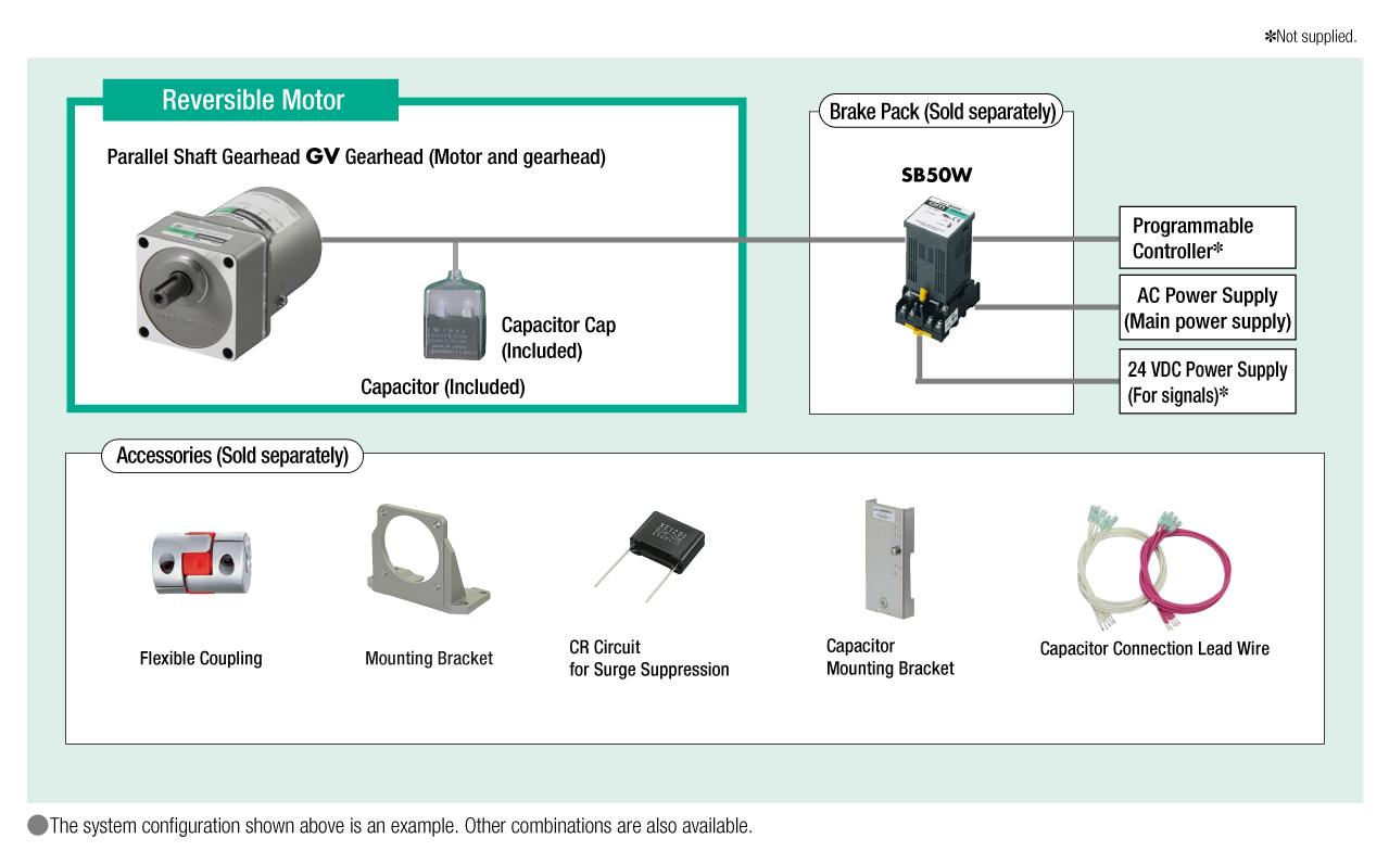
Cables and Accessories
close
close

close