Induction Motors
5IK40VEST2-GHR100S
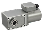
Geared Motor
| Product Classification | Product Name | List Price | Shipping Date |
|---|---|---|---|
| Geared Motor | 5IK40VEST2-GHR100S | - | Discontinued Product (31.3.2021 discontinued) |
Included
- Geared Motor, Mounting Screws, Parallel Key, Safety Cover, Operating Manual
Specifications
Data Download
Other Specifications
General Specifications
| Item | Specifications |
|---|---|
| Insulation Resistance | 100 MΩ or more when a 500 VDC megger is applied between the windings and the case after continuous operation under normal ambient temperature and humidity. |
| Dielectric Strength | No abnormality is observed when 1.5 kVAC (2.0 kVAC for three-phase 380/400/415 VAC) is applied at 50 Hz or 60 Hz between the motor coils and the case of the motor for 1 minute after continuous operation at normal ambient temperature and humidity. |
| Temperature Rise | Winding temperature rise is a max. of 80 °C, measured by the resistance change method after rated load continuous operation under normal ambient temperature and humidity. |
| Thermal Class | 130 (B) |
| Operating Ambient Temperature | 0~+40 °C (Non-freezing) |
| Operating Ambient Humidity | 85 % max. (Non-condensing) |
| Degree of Protection |
Terminal Box Type: IP66*
Lead Wire Type: IP20 Cable Type: IP40 |
Note
- No built-in overheat protection device (thermal protector).
When there is an overload or the output shaft is locked, use the electromagnetic switch and the inverter's electronic thermal function to prevent motor burnout.
- * The IP indication that shows the watertight and dust-resistant performance is specified under IEC60529 and IEC60034-5.
For materials and surface treatment, refer to the table below.
| Type | Output | Material/Surface Treatment | ||
|---|---|---|---|---|
| Point | Materials | Surface Treatment | ||
|
Terminal Box Type Stainless Steel Shaft |
30 W 40 W 100 W |
Motor Case | Aluminum |
Painting (excluding mounting surface) |
| Terminal Box | ||||
| Output Shaft | SUS303 | - | ||
| Screws |
Stainless Steel (externally facing screws only) |
- | ||
| 200 W | Motor Case | Aluminum | Anodizing | |
| Gear Case |
Painting (excluding mounting surface) |
|||
| Bracket | ||||
| Terminal Box | ||||
| Output Shaft | SUS303 | - | ||
| Screws |
Stainless Steel (externally facing screws only) |
- | ||
| Terminal Box Type |
100 W 200 W |
Motor Case | Aluminum |
Painting (excluding mounting surface) |
| Terminal Box | ||||
| Output Shaft | S45C | - | ||
| Screws |
Stainless Steel (externally facing screws only) |
- | ||
Permissible Radial Load and Permissible Axial Load
| Gear Ratio | 5 | 7.5 | 10 | 15 | 20 | 25 | 30 | 40 | 50 | 60 | 75 | 100 | 120 | 150 | 200 | 240 | ||
|---|---|---|---|---|---|---|---|---|---|---|---|---|---|---|---|---|---|---|
| Permissible Radial Load [N] |
Hollow Shaft | 10 mm From Mounting Surface | 1200 | 2200 | ||||||||||||||
| 20 mm From Mounting Surface | 1100 | 2000 | ||||||||||||||||
| Solid Shaft | 10 mm From the End of the Output Shaft | 900 | 1700 | |||||||||||||||
| 20 mm From the End of the Output Shaft | 1000 | 1850 | ||||||||||||||||
| Permissible Axial Load [N] | 350 | |||||||||||||||||
About Load Position
Calculating the Permissible Radial Load for Hollow Shaft Type
When the end of the load shaft being driven is not supported by a bearing, as shown in the figure on the right, calculate the permissible radial load using the following formula.
(This mechanism is the most demanding state in terms of radial load.)
- When the gear ratio is 5~40
- When the gear ratio is 50~240 gear ratio
Recommended Electromagnetic Switch
Always connect an electromagnetic switch when connecting the motor power supply.
Use an electromagnetic switch from the following product list, or an equivalent.
Set the rated current of the motor for the stabilized current of the thermal relay.
For the rated current of the motor, check the specifications for each product.
Fuji Electric FA Components & Systems Co., Ltd.
| Motor Output Power | Part Number | |
|---|---|---|
| 30 W, 40 W | SC11AAN-□ 10TD | |
| 60 W | SC11AAN-□ 10TF | |
| 100 W | SC11AAN-□ 10TH | |
| 200 W | Voltage 200~240 VAC | SC11AAN-□ 10TK |
| Voltage 380~415 VAC | SC11AAN-□ 10TH | |
- * The winding code is specified where the box □ is located in the part number.
| Rated Voltage | Winding Code | |
|---|---|---|
| 50 Hz | 60 Hz | |
| 200 VAC | 200-220 VAC | 2 |
| 200-220 VAC | 220-240 VAC | M |
| 220-240 VAC | 240-260 VAC | P |
| 346-380 VAC | 380-420 VAC | S |
| 380-400 VAC | 400-440 VAC | 4 |
| 415-440 VAC | 440-480 VAC | T |
Manufactured by Mitsubishi Electric Corporation
| Motor Output Power | Part Number | |
|---|---|---|
| 30 W, 40 W | MSO-T10 0.24A 200V AC200VAC | |
| 60 W | MSO-T10 0.35A 200V AC200VAC | |
| 100 W | MSO-T10 0.5A 200V AC200VAC | |
| 200 W | Voltage 200~240 VAC | MSO-T10 0.9A 200V AC200VAC |
| Voltage 380~415 VAC | MSO-T10 0.5A 400V AC400VAC | |
Usage with Inverter
When using in combination with an inverter, the setting frequency conditions of the inverter are as follows.
Refer to the operating manual for motor settings and precautions.
| Type | Product Name | Frequency |
|---|---|---|
| Right-Angle Hollow Shaft Hypoid Gearhead | 4IK30 | 100 Hz max. |
| 5IK40 | 80 Hz max. (60 Hz max. for gear ratio 10) | |
|
5IK100 7IK200 |
120 Hz max. | |
| Parallel Shaft Gearhead GV Gearhead Round Shaft Type |
4IK30
5IK40 5IK60 5IK100 7IK200 |
120 Hz max. |
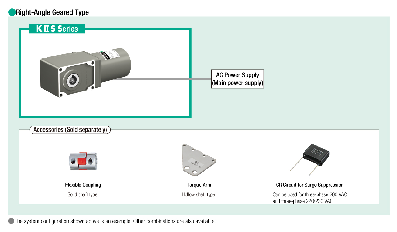
System Configuration