Stepper Motors RK Series (Without PE terminal)
RK564BC-H50
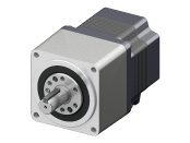
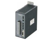
Geared Motor/Control Circuit
This product is currently no longer available for sale.
| Product Classification | Product Name | List Price | Shipping Date |
|---|---|---|---|
| Motor / Control Circuit | RK564BC-H50 | - | Discontinued Product (1.4.2016 discontinued) |
Included
- Motor, Control Circuit, Control I/O Connector, Parallel Key, Operating Manual
Specifications
Data Download
Other Specifications
Circuit Specifications
| Input Signals | Input Mode | Photocoupler input, Input resistance 220 Ω, Input current 7~20 mA photocoupler "ON": +4.5~5 V, photocoupler "OFF": 0~+1 V (voltage between terminals) |
|---|---|---|
| CW Pulse Signal (Pulse signal) |
CW direction operation command pulse signal (operation command pulse signal when in 1-pulse input mode), negative logic pulse input Pulse width 2.5 μs min., rise/fall time 2 μs max., pulse duty 50 % max. When the pulse input is turned from "ON" to "OFF," the motor rotates 1 step. Maximum input pulse frequency 200 kHz (at 50 % pulse duty) |
|
| CCW Pulse Signal (Rotation direction signal) |
CCW direction movement command pulse signal (for 1-pulse input mode, rotation direction signal Photocoupler "ON": CW, Photocoupler "OFF": CCW) Negative logic pulse input Pulse width 2.5 μs min., rise/fall time 2 μs max., pulse duty 50 % max. When the pulse input is turned from "ON" to "OFF," the motor rotates 1 step. Maximum input pulse frequency 200 kHz (at 50 % pulse duty) |
|
| All Windings Off Signal | When the photocoupler is "ON," the output current to the motor is turned "OFF," and the motor shaft can be turned by external force. (When turning the motor shaft with external force, release the electromagnetic brake.) When the photocoupler is "OFF," output current to the motor is turned "ON." |
|
| Electromagnetic Brake Release Signal* | When the photocoupler is "ON," the electromagnetic brake is released, and the motor can be operated. When the photocoupler is "OFF," the electromagnetic brake operates to hold the motor shaft. |
|
| Step Angle Select Input Signal | When the photocoupler is "OFF," DATA1 is selected; when the photocoupler is "ON," DATA2 is selected. | |
| Output Signals | Output Mode | Photocoupler and open-collector output External Use Conditions: 24 VDC max., 10 mA max. |
| Excitation Timing Signal | This signal is output when the excitation sequence is step "0." (Photocoupler "ON") Example) 0.72˚/step (number of divisions 1): output once every 10 pulses 0.072°/step (number of divisions - 10): Output once every 100 pulses |
|
| Overheat Signal | The output is turned OFF when the temperature of the driver heat sink rises to about 80 °C. (Photocoupler "OFF") | |
| Function | Automatic current cutback, automatic all windings off, step angle switching, pulse input mode switching, Electromagnetic brake function switching*Smooth drive function, power saving mode* |
|
| Indicator (LED) | Power supply input, excitation timing output signal, overheat output signal | |
| Cooling Method | Natural cooling method | |
- *Only for units with an electromagnetic brake.
General Specifications
General Specifications
| Specifications | Motor | Driver | |
|---|---|---|---|
| Thermal Class | 130 (B) [UL certified to 105 (A)] |
- | |
| Insulation Resistance | 100 MΩ or more when a 500 VDC megger is applied between the motor windings and the case under normal ambient temperature and humidity. |
At normal ambient temperature and humidity, the value measured at the following points with a 500 VDC megger is 100 MΩ min.
|
|
| Dielectric Strength | At normal ambient temperature and humidity, no abnormalities are observed when 1.5 kV at 50 Hz or 60 Hz (RK54□1.0 kV) is applied between the windings and the case of the motor for 1 minute. |
At normal ambient temperature and humidity, no abnormalities are observed when the following are applied for 1 minute.
|
|
| Operating Environment (when operating) |
Ambient Temperature |
-10~+50 °C (Non-freezing):
Standard type, TH・PS・PN geared type
0~+40 °C (Non-freezing):
Harmonic Geared Type
|
0~+50 °C (Non-freezing) |
| Ambient Humidity | 85 % max. (Non-condensing) | ||
| Atmosphere | No corrosive gases or dust. No exposure to water, oil or other liquids. (Motor with Standard Type Terminal Box: No corrosive gas. No exposure to oil) |
||
| Temperature Rise | 5-phase excitation at rated current, 80 °C max. at standstill Temperature rise of winding section at 80 °C or less (resistance change method) |
- | |
| Stop position accuracy*2 | ±3 minutes (±0.05˚) | - | |
| Shaft Runout | 0.05 T.I.R. (mm)*5 | - | |
| Radial Play*3 | 0.025 mm Max. (Load 5 N) | - | |
| Axial Play*4 | 0.075 mm Max. (Load 10 N) | - | |
| Concentricity of Installation Pilot to the Shaft | 0.075 T.I.R. (mm)*5 | - | |
| Perpendicularity of mounting surface to the shaft | 0.075 T.I.R. (mm)*5 | - | |
- *1
- (Only for types with electromagnetic brake)
- *2
- 0.72˚ is the value under no load. (The value changes with the size of the load.)
- *3
- Radial Play: Displacement in shaft position in the radial direction when a 5 N load is applied perpendicular to the tip of the motor shaft.
- *4
- Axial Play: Displacement in shaft position in the axial direction when a 10 N load is applied to the motor shaft in the axial direction.
- *5
- T.I.R. (Total Indicator Reading): The total dial gauge reading when the measurement section is rotated 1 revolution centered on the reference axis center.
Note
- Do not measure insulation resistance or perform a dielectric strength test while the motor and driver are connected.
Permissible Moment Load (Harmonic Geared Type)
| Motor Frame Size | Permissible Axial Load (N) | Permissible Moment Load (N·m) | Constant a (m) |
|---|---|---|---|
| 20 mm | 60 | 0.7 | 0.00485 |
| 30 mm | 140 | 2.9 | 0.0073 |
| 42 mm | 220 | 5.6 | 0.009 |
| 60 mm | 450 | 11.6 | 0.0114 |
The moment load can be calculated with the following formula.
-
Example 1: When an external force F (N) is applied to a position that extends L (m) horizontally from the center of the output flange
-
Example 2: When external force F (N) is applied to a position that extends in the vertical direction L (m) from the output flange-mounting surface.
Permissible Radial Load and Permissible Axial Load
| Type | Motor Frame Size | Motor Product Name | Gear Ratio | Permissible Radial Load | Permissible Axial Load | ||||
|---|---|---|---|---|---|---|---|---|---|
| Distance From Shaft End [mm] | |||||||||
| 0 | 5 | 10 | 15 | 20 | |||||
| High-Torque Type | 20 mm | PK213P, PK214P, PK513P | - | 12 | 15 | - | - | - | 3 |
| 28 mm | PK223P, PK224P, PK225P, PK523P, PK525P, PK523HP, PK525HP |
25 | 34 | 52 | - | - | 5 | ||
| 35 mm | PK233P, PK235P | 20 | 25 | 34 | 52 | - | 10 | ||
| 42 mm | PK244P, PK246P, PK544P, PK546P | 20 | 25 | 34 | 52 | - | 10 | ||
| 56.4 mm | PK264P, PK266P, PK268P | 61 | 73 | 90 | 110 | 160 | 20 | ||
| High-Torque and High-Efficiency Type | 42 mm | PKE243, PKE244, PKE245 | 20 | 25 | 34 | 52 | - | 10 | |
| High-Resolution Type / High-Resolution Type With Encoder |
28 mm | PK523PM, PK524PM, PK525PM, PK523HPM, PK524HPM, PK525HPM |
25 | 34 | 52 | - | - | 5 | |
| 42 mm | PK243M, PK244M, PK245M, PK544PM, PK546PM |
20 | 25 | 34 | 52 | - | 10 | ||
| 56.4 mm | PK264M, PK266M, PK268M | 54 | 67 | 89 | 130 | - | 20 | ||
| 60 mm | PK564PM, PK566PM, PK569PM | 90 | 100 | 130 | 180 | 270 | 20 | ||
| Standard Type / Standard Type Terminal Box Type / Standard Type With Encoder / Standard Type With electromagnetic brake |
42 mm | PK243, PK244, PK245, PK543 PK544, PK545 |
20 | 25 | 34 | 52 | - | 10 | |
| 50 mm | PK256, PK258 | 54 | 67 | 89 | 130 | - | 20 | ||
| 56.4 mm | PK264, PK266, PK268 | 54 | 67 | 89 | 130 | - | 20 | ||
| 60 mm | PK564, PK566, PK569 | 63 | 75 | 95 | 130 | 190 | 20 | ||
| 85 mm | PK596, PK599, PK5913, PK296 PK299, PK2913 |
260 | 290 | 340 | 390 | 480 | 60 | ||
| SH Geared Type | 28 mm | PK223P | 7.2, 9, 10, 18, 36 | 15 | 17 | 20 | 23 | - | 10 |
| 42 mm | PK243 | 3.6, 7.2, 9, 10, 18, 36, 50, 100 | 10 | 15 | 20 | 30 | - | 15 | |
| 60 mm | PK264 | 3.6, 7.2, 9, 10 | 30 | 40 | 50 | 60 | 70 | 30 | |
| 18, 36, 50, 100 | 80 | 100 | 120 | 140 | 160 | ||||
| TH Geared Type | 28 mm | PK523P | 7.2, 10, 20, 30 | 15 | 17 | 20 | 23 | - | 10 |
| 42 mm | PK543 | 3.6, 7.2, 10, 20, 30 | 10 | 14 | 20 | 30 | - | 15 | |
| 60 mm | PK564 | 70 | 80 | 100 | 120 | 150 | 40 | ||
| 90 mm | PK596 | 220 | 250 | 300 | 350 | 400 | 100 | ||
| PS Geared Type | 22 mm | PK513P | 4, 16 | 20 | 30 | - | - | - | 20 |
| 28 mm | PK523P | 5, 7.2, 10 | 45 | 60 | 80 | 100 | - | 40 | |
| 42 mm | PK545 | 5 | 70 | 80 | 95 | 120 | - | 100 | |
| 7.2 | 80 | 90 | 110 | 140 | - | ||||
| 10 | 85 | 100 | 120 | 150 | - | ||||
| PK543 | 25 | 120 | 140 | 170 | 210 | - | |||
| 36 | 130 | 160 | 190 | 240 | - | ||||
| 50 | 150 | 170 | 210 | 260 | - | ||||
| 60 mm | PK566 | 5 | 170 | 200 | 230 | 270 | 320 | 200 | |
| 7.2 | 200 | 220 | 260 | 310 | 370 | ||||
| 10 | 220 | 250 | 290 | 350 | 410 | ||||
| PK564 | 25 | 300 | 340 | 400 | 470 | 560 | |||
| 36 | 340 | 380 | 450 | 530 | 630 | ||||
| 50 | 380 | 430 | 500 | 600 | 700 | ||||
| 90 mm | PK599 | 5 | 380 | 420 | 470 | 540 | 630 | 600 | |
| 7.2 | 430 | 470 | 530 | 610 | 710 | ||||
| 10 | 480 | 530 | 590 | 680 | 790 | ||||
| PK596 | 25 | 650 | 720 | 810 | 920 | 1070 | |||
| 36 | 730 | 810 | 910 | 1040 | 1210 | ||||
| 50 | 820 | 910 | 1020 | 1160 | 1350 | ||||
| PN Geared Type | 28 mm | PK523P | 5, 7.2, 10 | 45 | 60 | 80 | 100 | − | 40 |
| 42 mm | PK544 | 5 | 80 | 95 | 120 | 160 | − | 100 | |
| 7.2 | 90 | 110 | 130 | 180 | − | ||||
| 10 | 100 | 120 | 150 | 200 | − | ||||
| 60 mm | PK566 | 5 | 240 | 260 | 280 | 300 | 330 | 200 | |
| 7.2 | 270 | 290 | 310 | 340 | 370 | ||||
| 10 | 300 | 320 | 350 | 380 | 410 | ||||
| PK564 | 25 | 410 | 440 | 470 | 520 | 560 | |||
| 36 | 360 | 410 | 480 | 570 | 640 | ||||
| 50 | 360 | 410 | 480 | 570 | 700 | ||||
| 90 mm | PK599 | 5 | 370 | 390 | 410 | 430 | 460 | 600 | |
| 7.2 | 410 | 440 | 460 | 490 | 520 | ||||
| 10 | 460 | 490 | 520 | 550 | 580 | ||||
| PK596 | 25 | 630 | 660 | 700 | 740 | 790 | |||
| 36 | 710 | 750 | 790 | 840 | 900 | ||||
| 50 | 790 | 840 | 890 | 940 | 1000 | ||||
| Harmonic Geared Type | 20 mm | PK513P | 50, 100 | 50 | 75 | - | - | - | 60 |
| 30 mm | PK523HP | 110 | 135 | 175 | 250 | - | 140 | ||
| 42 mm | PK543 | 180 | 220 | 270 | 360 | 510 | 220 | ||
| 60 mm | PK564 | 320 | 370 | 440 | 550 | 720 | 450 | ||
| 90 mm | PK596 | 1090 | 1150 | 1230 | 1310 | 1410 | 1300 | ||
- The product names are listed such that the product names are distinguishable.
- PS, PN Geared Type: Standard Input Rotation Speed: 1500 r/m, the value satisfies a calculated lifetime of 20,000 hours when either the permissible radial load or the permissible axial load are applied.
Radial Load and Axial Load
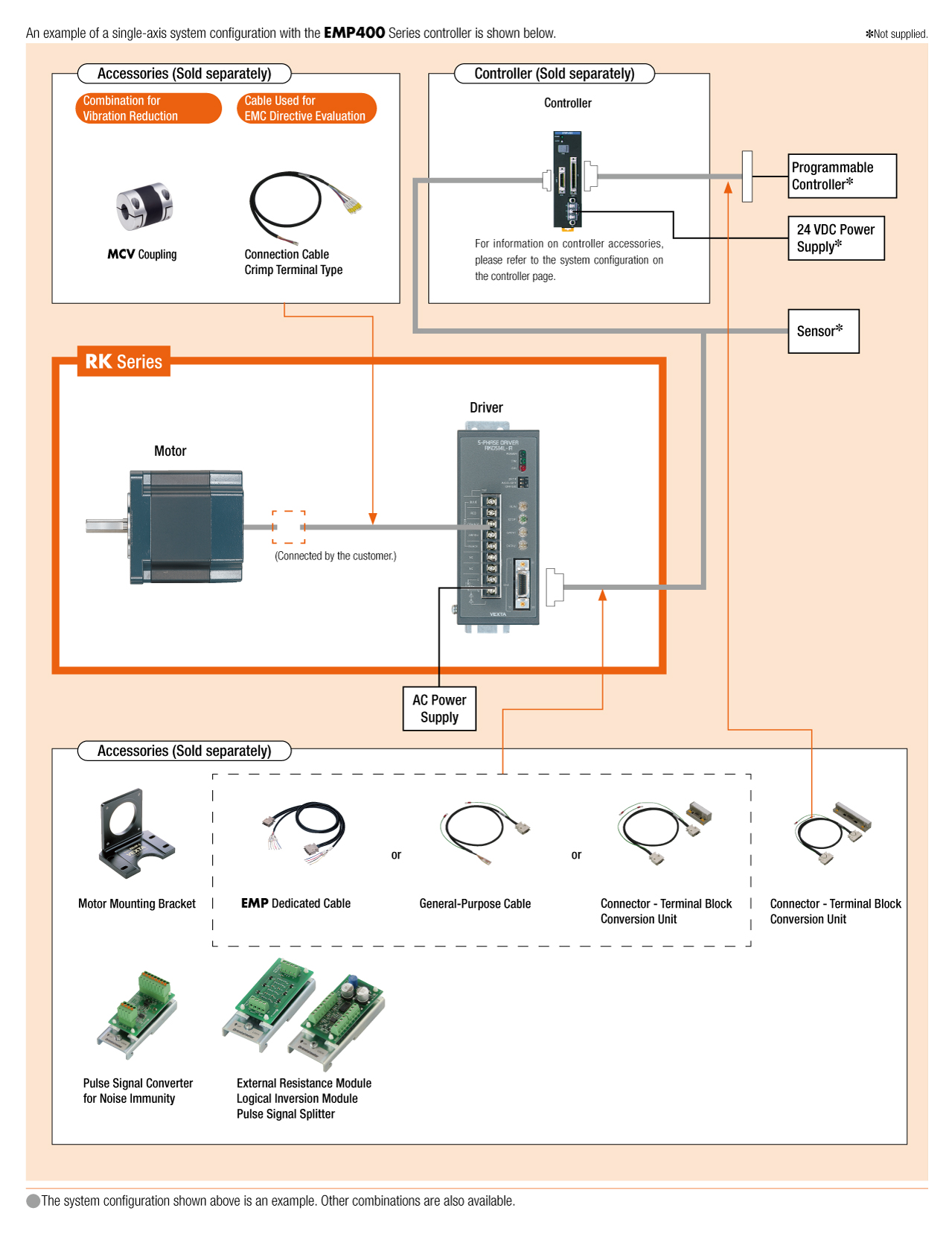
System Configuration
Cables and Accessories
close