AC Speed Control Motors MSS·W Series (RoHS non-compliant)
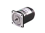
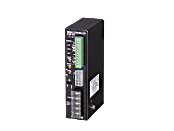
MSS315-411WU-6
Motor/Control Circuit
This product is currently no longer available for sale.
| Product Classification | Product Name | List Price | Shipping Date |
|---|---|---|---|
| Motor / Control Circuit | MSS315-411WU-6 | - | Discontinued Product (1.4.2015 discontinued) |
Included
- Motor and Driver Package: Motor, Control Circuit, Mounting Bracket for Control Circuit, External Speed Potentiometer, Extension Cable, Capacitor, Capacitor Cap, Operating Manual
Specifications
Data Download
Other Specifications
Common Specifications of the Circuit Section
| Item | MSP-1W | MSP-2W |
|---|---|---|
| Power Supply Input | Single-Phase 100 VAC±10% 50/60 Hz Single-Phase 100/115 VAC±10% 60 Hz |
Single-Phase 200 VAC±10% 50/60 Hz Single-Phase 220/230 VAC±10% 50/60 Hz |
| Functions | Speed control, no-contact instantaneous stop, no-contact bidirectional rotation, no-contact rotation speed switching, slow start/slow down (10 sec. at 1000 r/min with no load) |
|
| Control Power Supply | 24 VDC±10 %, min. 0.1 A | |
| Input Signal | Photocoupler Input External Contact Capacity: 26.4 VDC 10 mA CW/CCW/FREE/SPEED SET |
|
| Speed Setting Methods | Set 1 method from the following.
|
|
General Specifications
| Item | Motor | Speed Controller | |
|---|---|---|---|
| Insulation Resistance | After rated operation at normal ambient temperature and humidity, the measurement between the coils and the case is 100 MΩ min. using a 500 VDC megger. | After rated operation at normal ambient temperature and humidity, the value measured with a 500 VDC megger between the power supply input terminal and the protective earth terminal, and between the power supply input terminal and the signal terminal is min. 100 MΩ. | |
| Dielectric Strength | No abnormality is observed even with an application of 1.5 kVAC at 50 Hz or 60 Hz between the coils and the case for 1 minute after rated operation at normal ambient temperature and humidity. | After rated operation at normal ambient temperature and humidity, no abnormality is observed even if 50 Hz or 60 Hz, 1.5 kVAC is applied between the power supply input terminal and the protective earth terminal for 1 minute. In addition, no abnormality is observed even after 50 Hz or 60 Hz, 2.3 kVAC (3.0 kV for MSP-2W) is applied between the power supply input terminal and the signal input terminal for 1 minute. | |
| Temperature Rise | After a no load rated operation at normal ambient temperature and humidity, the winding temperature rise measured by the resistance change method with the gearhead or an equivalent heat sink*attached to the motor is 80 °C max. | - | |
| Overheat Protective Device |
The MSS206 Type is impedance protected. All other motors have a built-in thermal protector (automatic return type). Open: 130±5℃ Return: 82±15℃ |
- | |
| Operating Environment | Ambient Temperature | 110/115 V, 220/230 V: -10~+40°C (Non-freezing) 100 V, 200 V: -10~+50°C (Non-freezing) |
0∼+40 °C (Non-freezing) |
| Ambient Humidity | 85 % max. (Non-condensing) | ||
| Altitude | Up to 1000 m above sea level | ||
| Thermal Class | 130(B) | - | |
| Degree of Protection |
MSS206, MSS315, MSS 425, MSS 540 Type: IP20 MSS560, MSS590 Type: IP40 |
IP10 | |
- *Heat Sink Size (Material: Aluminum)
| Motor Type (Output power) | Size (mm) | Thickness (mm) |
|---|---|---|
| MSS206 Type (6 W) | 115x115 | 5 |
| MSS315 Type (15 W) | 125x125 | |
| MSS 425 Type (25 W) | 135x135 | |
| MSS 540 Type (40 W) | 165x165 | |
| MSS560 Type (60 W) | 200x200 | |
| MSS590 Type (90 W) | 200x200 |
Note
- Do not measure insulation resistance or perform a dielectric strength test while the motor and speed controller are connected.
Cables and Accessories
close