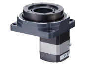
Hollow Rotary Actuators DGII Series
DG85R-ARACD2-1

Actuator/Control Circuit
| Product Classification | Product Name | List Price | Shipping Date |
|---|---|---|---|
| Actuator / Control Circuit | DG85R-ARACD2-1 | 2,169.00 € | Discontinued Product (31.3.2025 discontinued) |
Included
- Actuator, Circuit, Cable for motor (1 m), Connector for Regeneration Resistor Input/Main Power Input Terminals, Sensor Signal Connector, Input Signal Connector, Output Signal Connector, 24 VDC Power Supply Input/Regeneration Resistor Thermal Input/Electromagnetic Brake Output Terminal, Connector Wiring Lever
Specifications
Dimensions
Data Download
Other Specifications
The Settings of Resolution of output table (minimum step angle)
The minimum step angle of the output table for the built-in controller type can be set by the driver parameters (electronic gear A and electronic gear B).
The formula for calculating the minimum step angle of the output table is shown below.
To set the minimum step angle of the output table to 0.1 [˚], set electronic gear A to 5 and electronic gear B to 1.
An example calculation is shown below.
- For a detailed description of electronic gears, refer to the AR Series user manual.
- You can also use the technical support tool to help you set up your electronic gear.
General Specifications (Actuator)
| Installed Motor | AR Series Equipped AC Input | |
|---|---|---|
| Thermal Class | 130 (B) | |
| Insulation Resistance | 100 MΩ or more when a 500 VDC megger is applied between the following places:
|
|
| Dielectric Strength | Sufficient to withstand the following for 1 minute:
|
|
| Operating Environment (When operating) |
Ambient Temperature | 0~+50 °C (Non-freezing) When home-sensor set (accessory) is installed: 0~+40 °C (Non-freezing) |
| Ambient Humidity | 85 % max. (Non-condensing) | |
| Atmosphere | No corrosive gases or dust. No exposure to water, oil or other liquids. | |
Note
- Do not perform the insulation resistance test or dielectric strength test while the actuator and circuit are connected.
Circuit Specifications
| Positioning Function Built-in Type |
Pulse Input Type | ||
|---|---|---|---|
| Maximum Input Pulse Frequency | − | Line Driver Output by Host Controller: 500 kHz (at 50 % duty) Open-Collector Output by Host Controller: 250 kHz (at 50 % duty)*1 Negative Logic Pulse Input (Initial value) |
|
| Number of Positioning Data Sets | 64 Points | − | |
| Positioning Operation | Independent | ◯ | − |
| Linked | ◯ | − | |
| Linked 2 | ◯ | − | |
| Sequential | ◯ | − | |
| Direct | ◯ | − | |
| Continuous Operation | ◯ | − | |
| JOG Operation | ◯ | − | |
| Return-To-Home Operation | ◯ | − | |
| Test Operation | ◯ | ◯*2 | |
| Control Module OPX-2A |
◯ | ◯ | |
| Support Software MEXE02 |
◯ | ◯ | |
- *1
- The value when the general-purpose cable (CC36D1E) (sold separately) is used.
- *2
- Setting by extended function (MEXE02)
Circuit General Specifications
|
|
AC Input | DC Input | |||
|---|---|---|---|---|---|
| Built-In Controller Type | Pulse Input Type | Built-In Controller Type | Pulse Input Type | ||
| Insulation Resistance*1 |
|
|
− | ||
| Dielectric Strength*2 |
|
|
|
− | |
| Operating Environment (When operating) |
Ambient Temperature | 0~+55 °C*3
(Non-freezing) |
0~+50 °C*3
(Non-freezing) |
0~+50 °C (Non-freezing) |
|
| Ambient Humidity | 85 % max. (Non-condensing) | ||||
| Atmosphere | No corrosive gases or dust. No exposure to water, oil or other liquids. | ||||
| Degree of Protection | IP10 | IP20 | IP10 | IP20 | |
- *1
- The measured value is 100 MΩ min. when a 500 VDC megger is applied between 2 points in the table.
- *2
- No abnormality is observed after 1 minute of application under the conditions shown in the table.
- *3
- When installing a heat sink equivalent to an aluminum plate min. 200×200 mm, thickness 2 mm
Note
- Do not perform the insulation resistance test or dielectric strength test while the actuator and circuit are connected.
RS-485 Communication Specifications
| Protocol | Modbus RTU mode |
|---|---|
| Electrical Characteristics | EIA-485 Compliant, straight cable Use twisted-pair cables (TIA/EIA-568B CAT5e or better recommended), the max. total extension length is 50 m.* |
| Mode | Half duplex and asynchronous mode (data: 8 bits, stop bit: 1 bit or 2 bits, parity: none, even, or odd) |
| Transmission Rate | Selectable from 9,600 bps, 19,200 bps, 38,400 bps, 57,600 bps and 115,200 bps. |
| Connection Type | Up to 31 drivers can be connected to one host controller. |
- *If a specific wiring and layout causes the motor cable or power supply cable to generate a noise problem, shield the cable or use ferrite cores.
Standards
Regulations and Standards Materials
Documents about compliance with regulations and standards can be downloaded from the "Data Download" tab on the product details page.
(The types of files available for download vary by product.)
Explanations of the Global Laws, Regulations and Standards can be found here.
Information about our compliance with regulations and standards for each of our product series can be found here.
Hazardous Substances
The product does not contain any substances (10 substances) exceeding the regulation values of the RoHS Directive (2011/65/EU, 2015/863/EU).
For more information about compliance with regulations on chemical substances in Oriental Motor's Products, click here.
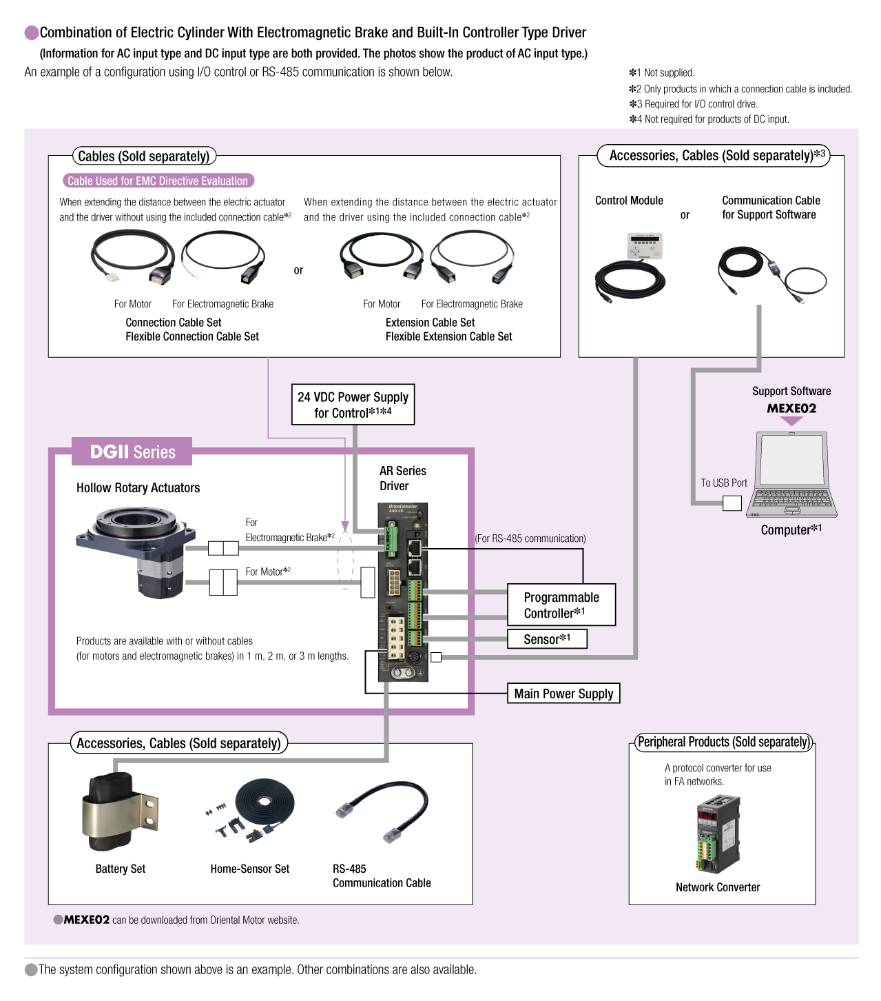
System Configuration
Related Products
| Products | Features | ||
|---|---|---|---|
NETC02-CC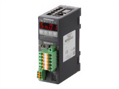
|
Features |
[CC-Link Ver. 2 Compatible] By supporting CC-Link Ver.2, you can simplify the ladder program and shorten the communication time for data sending and receiving. |
|
| Products |
NETC01-ECT
|
Features |
[EtherCAT Compatible] |
Cables and Accessories