Hollow Rotary Actuators DGII Series (Former type)
DG130R-ARAA-3
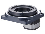
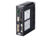
Actuator/Control Circuit
This product is currently no longer available for sale.
| Product Classification | Product Name | List Price | Shipping Date |
|---|---|---|---|
| Actuator / Control Circuit | DG130R-ARAA-3 | - | Discontinued Product (1.4.2017 discontinued) |
Included
- Actuator, Control Circuit, Motor Cable (3 m), I/O Signal Connector, Connector for Regeneration Resistor Input/Main Power Input Terminals, Connector for 24 VDC Power Supply Input/Regeneration Resistor Thermal Input, Connection lever, Operation manual
Specifications
Other Specifications
Driver Circuit Specifications
| Positioning Function Built-in Type |
Pulse Input Type | ||
|---|---|---|---|
| Maximum Input Pulse Frequency | − | Line Driver output by host controller: 500 kHz (at 50 % duty) Open-collector output by host controller: 250 kHz (at 50 % duty)* |
|
| Number of Positioning Data Sets | 64 Points | − | |
| Positioning Operation | Independent | ◯ | − |
| Linked | ◯ | − | |
| Linked 2 | ◯ | − | |
| Sequential | ◯ | − | |
| Direct | ◯ | − | |
| Continuous Operation | ◯ | − | |
| JOG Operation | ◯ | − | |
| Return-to-Home Operation | ◯ | − | |
| Test Operation | ◯ | ◯ | |
| Absolute Backup System |
◯ | − | |
| Control Module OPX-2A |
◯ | ◯ | |
| Support Software MEXE02 |
◯ | ◯ | |
- * The value is when using a general-purpose cable (sold separately).
RS-485 Communication Specifications
| Protocol | Modbus Protocol (Modbus RTU mode) |
|---|---|
| Electrical Characteristics | EIA-485 Compliant Use twisted-pair cables (TIA/EIA-568B CAT5e or better recommended). The max. total extension length is 50 m. |
| Transmission/Reception Mode | Half duplex |
| Transmission Rate | 9600bps/19200bps/38400bps/57600bps/115200bps |
| Physical Layer | Asynchronous mode (data: 8 bits, stop bit: 1 bit or 2 bits, parity: none, even, or odd) |
| Connection Type | Up to 31 units can be connected to a single programmable controller (master device). |
General Specifications
DC Input
|
|
Motor | Driver | ||
|---|---|---|---|---|
| Built-in Controller Type | Pulse Input Type | |||
| Thermal Class | 130 (B) | − | ||
| Insulation Resistance |
100 MΩ or more when 500 VDC megger is applied between the following places.
|
100 MΩ or more when 500 VDC megger is applied between the following places.
|
- | |
| Dielectric Strength |
Sufficient to withstand the following for 1 minute:
|
Sufficient to withstand the following for 1 minute:
|
- | |
| Operating Environment (When Operating) |
Ambient Temperature | 0~+50 °C (Non-freezing) When home-sensor set (accessory) is installed: 0~+40 °C (Non-freezing) |
0~+50 °C (Non-freezing) | |
| Ambient Humidity | 85 % max. (Non-condensing) | |||
| Atmosphere | No corrosive gases or dust. No exposure to water, oil or other liquids. | |||
| Degree of Protection | Single shaft: IP40 (IP20 for motor part connector) Double shaft: IP20 |
IP10 | IP20 | |
Note
- Do not perform the insulation resistance test or the dielectric strength test while the actuator and driver are connected.
AC Input
| Motor | Driver | |||
|---|---|---|---|---|
| Built-in Controller Type | Pulse Input Type | |||
| Thermal Class | 130 (B) | − | ||
| Insulation Resistance |
100 MΩ or more when a 500 VDC megger is applied between the following places:
|
100 MΩ or more when a 500 VDC megger is applied between the following places:
|
||
| Dielectric Strength |
Sufficient to withstand the following for 1 minute:
|
Sufficient to withstand the following for 1 minute: | ||
|
|
|||
| Operating Environment (When Operating) |
Ambient Temperature | 0~+50 °C (Non-freezing) When home-sensor set (accessory) is installed: 0~+40 °C (Non-freezing) |
0~+55 °C (Non-freezing)* | 0~+50 °C (Non-freezing)* |
| Ambient Humidity | 85 % max. (Non-condensing) | |||
| Atmosphere | No corrosive gases or dust. No exposure to water, oil or other liquids. | |||
| Degree of Protection | Single shaft with electromagnetic brake: IP40 (motor part connector is IP20) Double shaft: IP20 |
IP10 | IP20 | |
- * When installing a heat sink equivalent to an aluminum plate min. 200×200 mm, thickness 2 mm
Note
- Do not perform the insulation resistance test or the dielectric strength test while the actuator and driver are connected.
System Configuration
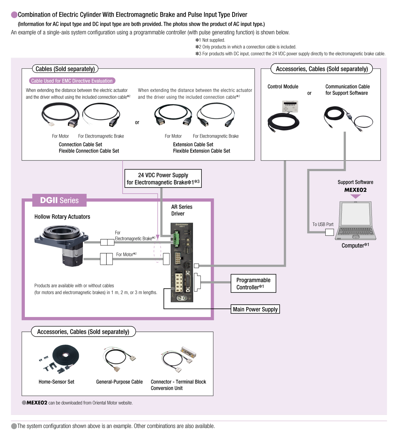
Cables and Accessories
close