Stepper Motors CSK Series
CSK243AP-SG100
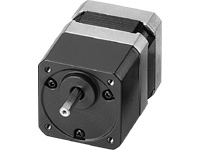
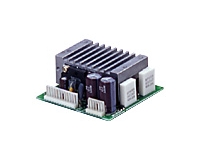
Motor/Control Circuit
This product is currently no longer available for sale.
| Product Classification | Product Name | List Price | Shipping Date |
|---|---|---|---|
| Motor / Control Circuit | CSK243AP-SG100 | - | Discontinued Product (1.4.2017 discontinued) |
Included
- Motor, Control Circuit, Connector Housing, Contact, Mounting Screw, Operating Manual
Specifications
Data Download
Other Specifications
General Specifications
| Specifications | Motor | Driver | |
|---|---|---|---|
| Insulation Class | Class B (130 °C) | - | |
| Insulation Resistance | 100 MΩ or more when a 500 VDC megger is applied between the motor windings and the case under normal ambient temperature and humidity. | - | |
| Dielectric Strength | Under normal ambient temperature and humidity, no abnormalities were observed even if 1.0 kV at 50 Hz or 60 Hz is applied between the windings and the case of the motor for 1 minute. | - | |
| Operating Environment (when operating) |
Ambient Temperature | -10~+50 °C (Non-freezing) | 0~+40 °C (Non-freezing) |
| Ambient Humidity | 85 % max. (Non-condensing) | ||
| Atmosphere | No corrosive gases or dust. No exposure to water, oil or other liquids. | ||
| Temperature Rise | 2-phase excitation at rated voltage, winding temperature rise to 80 °C max. at standstill (resistance change method) | - | |
| Stop position accuracy*1 | ±3 arcmin (±0.05˚) | - | |
| Shaft Runout | 0.05 T.I.R. (mm)*4 | - | |
| Radial Play*2 | 0.025 mm Max. (Load 5 N) | - | |
| Axial Play*3 | 0.075 mm Max. (Load 10 N) | - | |
| Concentricity of Installation Pilot to the Shaft | 0.075 T.I.R. (mm)*4 | - | |
| Perpendicularity of mounting surface to the shaft | 0.075 T.I.R. (mm)*4 | - | |
- *1
- This is the value at full step and no load (Varies depending on the size of the load).
- *2
- Radial Play: Displacement in shaft position in the radial direction when a 5 N load is applied perpendicular to the tip of the motor shaft.
- *3
- Axial Play: Displacement in shaft position in the axial direction when a 10 N load is applied to the motor shaft in the axial direction.
- *4
- T.I.R. (Total Indicator Reading): The total dial gauge reading when the measurement section is rotated 1 revolution centered on the reference axis center.
Note
- Do not measure insulation resistance or perform a dielectric strength test while the motor and driver are connected.
Permissible Radial Load and Permissible Axial Load
Unit: N
| Product Name | Gear Ratio | Permissible Radial Load | Permissible Axial Load | ||||
|---|---|---|---|---|---|---|---|
| Distance From Shaft End [mm] | |||||||
| 0 | 5 | 10 | 15 | 20 | |||
| CSK243-□P CSK244-□P CSK245-□P |
- | 20 | 25 | 34 | 52 | - | Less than or equal to motor weight |
| CSK256-□P CSK258-□P |
54 | 67 | 89 | 130 | - | ||
| CSK264-□P CSK266-□P CSK268-□P |
54 | 67 | 89 | 130 | - | ||
| CSK296-□P CSK299-□P CSK2913-□P |
260 | 290 | 340 | 390 | 480 | ||
| CSK264J□P CSK266J□P CSK267J□P CSK269J□P |
50 | 60 | 75 | 100 | 150 | ||
| CSK223P□P CSK224P□P CSK225P□P |
25 | 34 | 52 | - | - | ||
| CSK233P□P CSK235P□P |
20 | 25 | 34 | 52 | - | ||
| CSK244P□P CSK246P□P |
20 | 25 | 34 | 52 | - | ||
| CSK243M□P CSK244M□P CSK245M□P |
20 | 25 | 34 | 52 | - | ||
| CSK264M□P CSK266M□P CSK268M□P |
54 | 67 | 89 | 130 | - | ||
| CSK223□P-SG■ | 7.2, 9, 10, 18, 36 |
15 | 17 | 20 | 23 | - | 10 |
| CSK243□P-SG■ | 3.6, 7.2, 9, 10, 18, 36, 50, 100 |
10 | 15 | 20 | 30 | - | 15 |
| CSK264□P-SG■ | 3.6, 7.2, 9, 10 | 30 | 40 | 50 | 60 | 70 | 30 |
| 18, 36, 50, 100 | 80 | 100 | 120 | 140 | 160 | 30 | |
| CSK296□P-SG■ | 3.6, 7.2, 9, 10, 18, 36 |
220 | 250 | 300 | 350 | 400 | 100 |
- Either A or B indicating the motor shaft type is specified where the box □ is located in the product name.
A number indicating the gear ratio is specified where the box ■ is located in the product name.
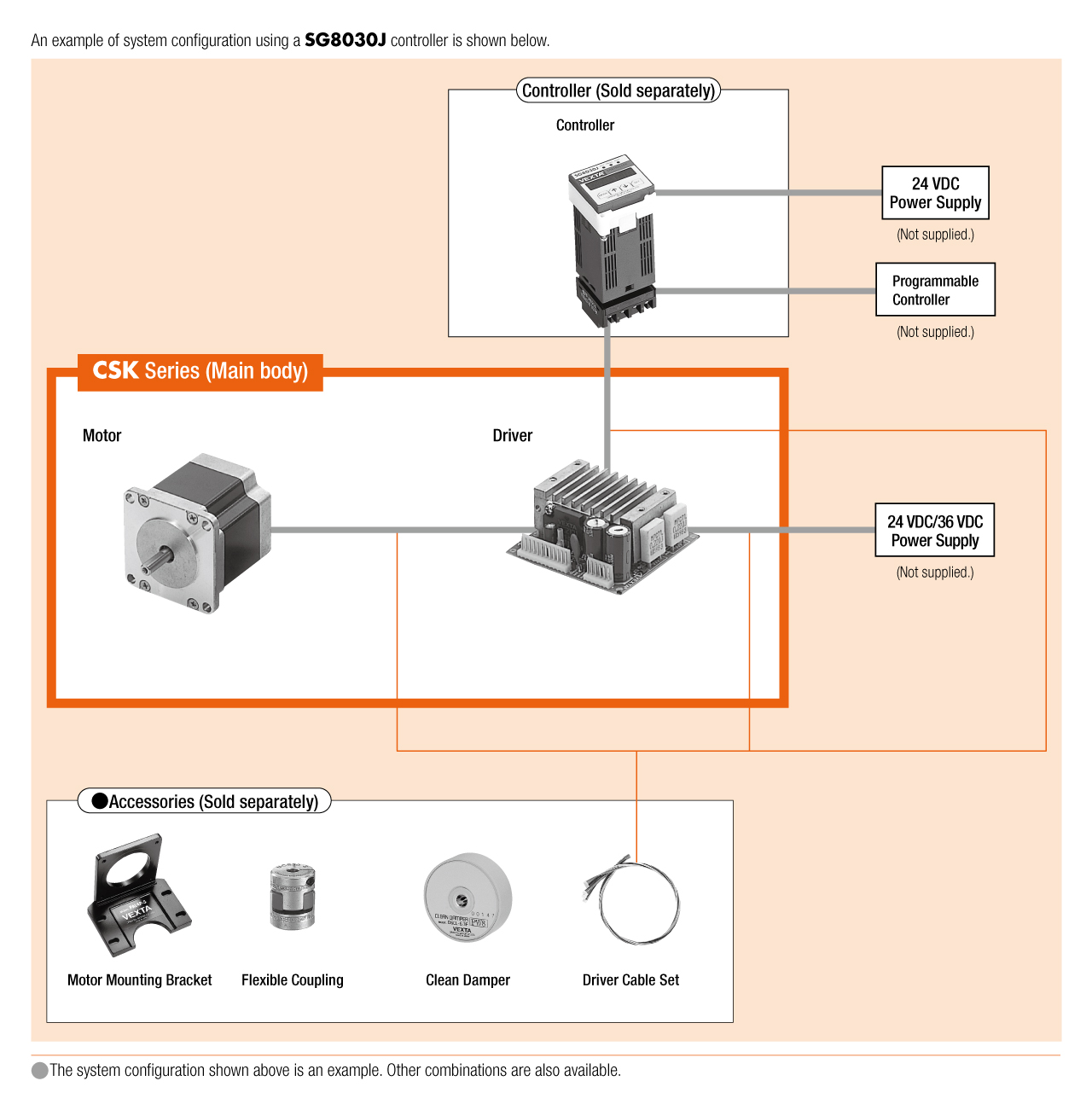
System Configuration
Cables and Accessories
close