Brushless Motors BLA Series
BLA550CB-15
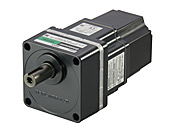
Combi geared motor
This product is currently no longer available for sale.
| Product Classification | Product Name | List Price | Shipping Date |
|---|---|---|---|
| Combi geared motor | BLA550CB-15 | - | Discontinued Product (31.3.2019 discontinued) |
Included
- Motor, Gearhead, Connector for CN1, CN2 Connector , Mounting Screws, Parallel Key, Operating Manual
Specifications
Data Download
Other Specifications
Specifications
| Item | Specifications | |
|---|---|---|
| Speed Setting Methods | Digital Setting: Max. 2 speeds (setting by speed teaching is possible) | |
| Acceleration Time and Deceleration Time | 0.5~15 seconds | |
| Input Signal | Photocoupler Input Input Resistance: 680 Ω or 5.1 kΩ Operated by internal power supply: 6.0 VDC Connectable external DC power supply: 12 VDC-10% ~ 24 VDC+20% current 100 mA min. Signals can be assigned to general-purpose inputs X0 and X1 as desired. [ ]: Factory setting [FWD input], [REV input], stop mode selection input, speed setting selection input, alarm reset input, external stop signal input |
|
| Output Signals | Open-Collector Output External use conditions: Control voltage 4.5~30.0 VDC Current max. 40 mA Speed Output: min. 5 mA Signals can be assigned to general-purpose output Y0 as desired [ ]: Factory setting Output during motor operation, alarm output 2, warning output, [alarm output 1], speed output |
|
| Protective Function | When the following protective functions are activated, the motor will stop spontaneously and an alarm code will be displayed: (External stop is an instantaneous stop.) Overcurrent, main circuit overheat, overvoltage, undervoltage, sensor error, overload, over-speed, EEPROM error, initial sensor error, prevention of operation at power-on, external stop |
|
| Insulation Resistance | After continuous operation at normal ambient temperature and humidity, the value measured with a 500 VDC megger between the motor winding and motor case, between the power supply input and protective earth terminal, and between the power supply input and I/O terminal is 100 MΩ min. | |
| Dielectric Strength | After continuous operation at normal ambient temperature and humidity, no abnormality is observed when 50 Hz, 1.85 kVAC is applied between the motor winding and motor case, and between the power supply input and protective earth terminal, and 50 Hz, 3.0 kVAC is applied between the power supply input and I/O terminal for 1 minute. | |
| Temperature Rise | After rated continuous operation at normal ambient temperature and humidity, the temperature rise of the motor winding measured by the thermocouple method is 60 °C max. and that of the motor case surface is 50 °C max. *1 | |
| Operating Environment | Ambient Temperature | 0∼+40 °C (Non-freezing) |
| Ambient Humidity | 85 % max. (Non-condensing) | |
| Altitude | Less than 1000 m above sea level | |
| Atmosphere | Cannot be used in special environments such as corrosive gas, no dust, radioactive materials, magnetic fields, or vacuums | |
| Vibration | Not subject to continuous vibration or excessive shock In conformance with JIS C 60068-2-6, "Sine-wave vibration test method" Frequency Range: 10~55 Hz, Half Amplitude: 0.15 mm, Sweep Direction: 3 directions (X, Y, Z), Number of Sweeps: 20 times |
|
| Storage Conditions*2 | Ambient Temperature | -25 °C~+70 °C (non-freezing) |
| Ambient Humidity | 85 % max. (Non-condensing) | |
| Altitude | Up to 3000 m above sea level | |
| Thermal Class | 120 (E) | |
| Degree of Protection | IP20 | |
- *1
- Attach round shaft types to a heat sink (Material: aluminum) of one of the following sizes to maintain a motor case surface temperature of 90 °C max.
200 × 200 mm, 5 mm thickness - *2
- The value for storage condition applies to short periods such as the period during transport.
Permissible Radial Load and Permissible Axial Load
| Gear Ratio | 5 | 9 | 15 | 30 | 50 | 100 | 180 | ||
|---|---|---|---|---|---|---|---|---|---|
| Speed Control Range [r/min] | 12~480 | 6.7~267 | 4~160 | 2~80 | 1.2~48 | 0.6~24 | 0.3~13 | ||
| Permissible Torque [N·m] | Motor Shaft Rotation Speed |
At 60~2000 r/min | 1.1 | 2 | 3.4 | 6.5 | 10.8 | 21.5 | 30 |
| At 2400 r/min | 0.95 | 1.7 | 2.8 | 5.4 | 9 | 18.1 | 30 | ||
| Permissible Inertia [J: 10--4kg·m2] | 10 | 32.4 | 90 | 360 | 1000 | 1000 | 1000 | ||
| Permissible Radial Load [N] | 10 mm From the End of the Output Shaft | 400 | 450 | 500 | |||||
| 20 mm From the End of the Output Shaft | 500 | 600 | 700 | ||||||
| Permissible Axial Load [N] | 150 | ||||||||
System Configuration
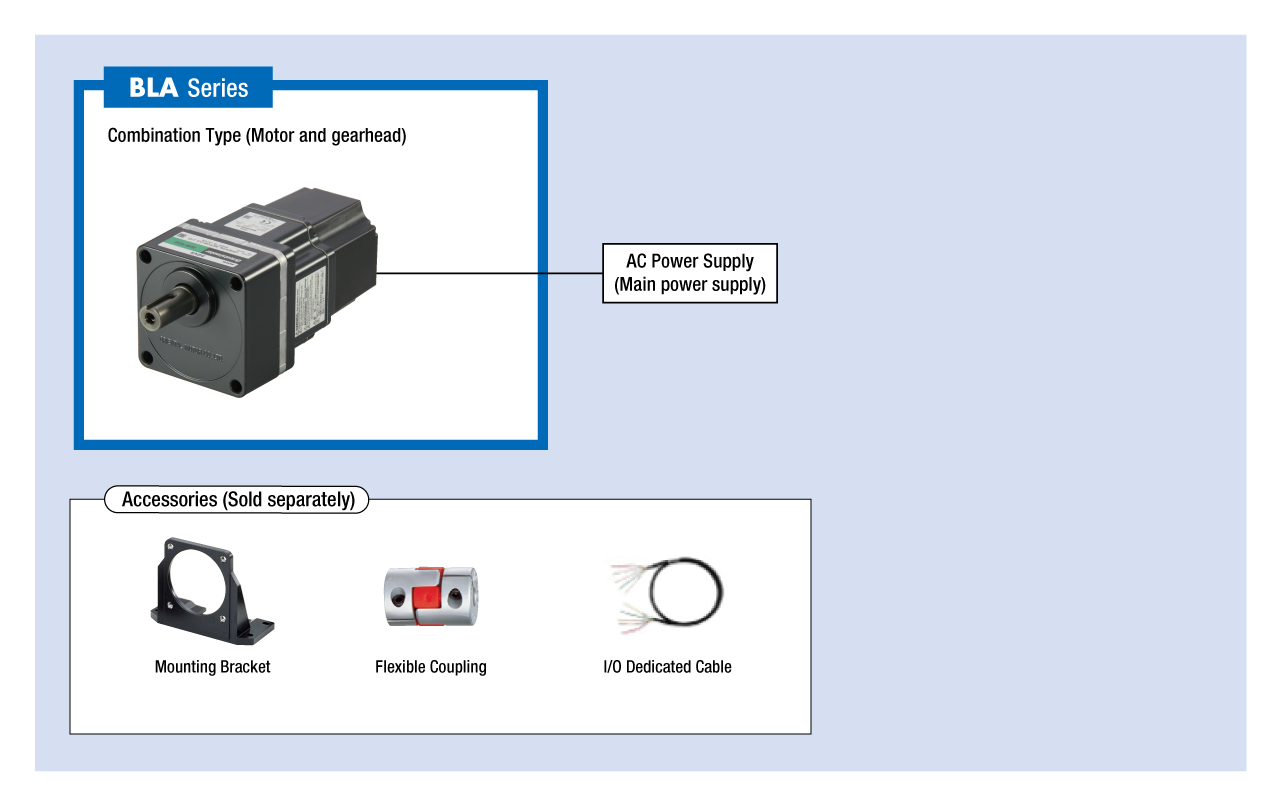
Cables and Accessories
close