Induction Motors
BHI82ET-100
Combi geared motor
This product is currently no longer available for sale.
| Product Classification | Product Name | List Price | Shipping Date |
|---|---|---|---|
| Combi geared motor | BHI82ET-100 | - | Discontinued Product (31.3.2022 discontinued) |
Included
- Motor, Gearhead, Capacitor, Capacitor Cap, Installation Screws, Parallel Key, Operating Manual
Specifications
Dimensions
Data Download
Other Specifications
General Specifications
| Item | Specifications |
|---|---|
| Insulation Resistance | After rated operation at normal ambient temperature and humidity, the measurement between the coils and the case is 100 MΩ min. using a 500 VDC megger. |
| Dielectric Strength | After continuous rated operation at normal ambient temperature and humidity, no abnormalities were observed even with an application of 1.5 kV(three-phase 380/400/415 VAC is 2.0 kVAC) at 50 Hz or 60 Hz between the coils and the case for 1 minute. |
| Temperature Rise | After a gearhead or equivalent heat sink*is connected for rated operation at normal ambient temperature and humidity, the measurement value of the winding temperature rise is 70 °C max. using the resistance change method. |
| Thermal Class | 130(B) |
| Overheat Protective Device | Built-in thermal protector (automatic return type) Open: 150 ± 5 °C, Return: 96 ± 15 °C Three-phase 380/400/415 V Type Open: 130 ± 5 °C, Return: 83 ± 15 °C |
| Operating Ambient Temperature | Single-phase 100 V, single-phase 200 V, three-phase 200 V: -10~+50 °C (Non-freezing) Other voltages: -10~+40 °C (Non-freezing) |
| Operating Ambient Humidity | 85 % max. (Non-condensing) |
| Degree of Protection |
Lead wire type: IP40 Terminal box type: IP54 (Excluding mounting surface of round shaft type) |
- *Heat Sink Size: 230 × 230 mm, 5 mm thickness (Material: aluminum)
Permissible Radial Load and Permissible Axial Load of Gearhead
| Product Name | Gear Ratio | Maximum Permissible Torque N·m |
Permissible Radial Load N | Permissible Axial Load N |
|
|---|---|---|---|---|---|
| From Shaft End 10 mm |
From Shaft End 20 mm |
||||
| BH6G2-□ | 3~36 | 40 | 550 | 800 | 200 |
| 50~180 | 650 | 1000 | |||
| BH8G-□ | 30~180 | 70 | 1400 | 1700 | 400 |
| BH6G2-□RH | 5~36 | 60 | 1200* | 1100* | 300 |
| 50~180 | 2200* | 2000* | |||
| BH6G2-□RA | 5~36 | 60 | 900 | 1000 | 300 |
| 50~180 | 1700 | 1850 | |||
- *The permissible radial load is the value at the distance from the flange-mounting surface.
Calculating the Permissible Radial Load for Hollow Shaft Type
When the end of the load shaft being driven is not supported by a bearing as shown in the figure on the right, calculate the permissible radial load using the following formula. (This mechanism is the most demanding state in terms of radial load.)
System Configuration
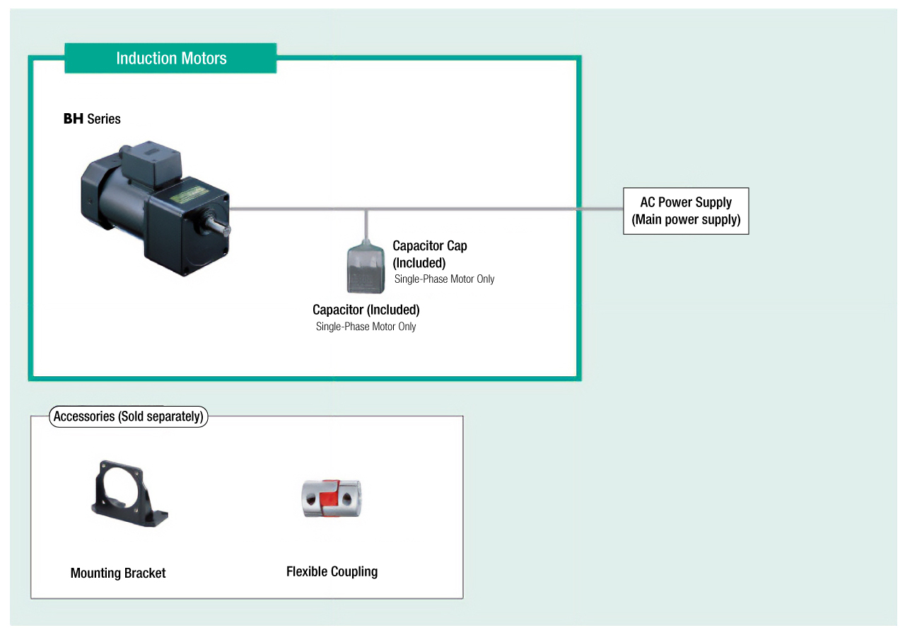
Cables and Accessories
close
close