Brushless Motors AXH Series
AXH5100K-10
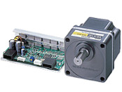
Gearhead / Motor / Control Circuit
This product is currently no longer available for sale.
| Product Classification | Product Name | List Price | Shipping Date |
|---|---|---|---|
| Gearhead / Motor / Control Circuit | AXH5100K-10 | - | Discontinued Product (31.3.2022 discontinued) |
Included
- Motor, Control Circuit, Gearhead, Parallel Key, I/O Signal Cable, Power Supply Cable, Operating Manual
Specifications
Data Download
Other Specifications
Common Specifications
| Item | Specifications |
|---|---|
| Speed Setting Methods |
Set 1 method from the following.
|
| Multi-Speed Setting Methods | 2-Speed 1-Speed by Internal Speed Potentiometer (1 pc), 1-Speed by External Speed Potentiometer (accessory PAVR-20KZ), or External DC Voltage (0~5 VDC) |
| Input Signals | C-MOS Negative Logic Input Method Operated by Internal Power Supply Common to start/stop input, run/brake input, rotation direction switching input, speed setting mode selection input, and alarm reset input |
| Output Signals | Open-collector output Operated by external power supply Operating conditions 26.4 VDC max. 10 mA max. Common to alarm output and speed output |
| Protective Functions* |
When the following protective functions are activated, the motor will come to a coasting stop, and the alarm output will be turned OFF. The alarm LED of the driver blinks the number of times indicated in parentheses ( ).
|
| Maximum Extension Distance | Between motor and driver 2 m (when an accessory connection cable is used) |
| Time Rating | Continuous |
- *The AXH series cannot control the speed control of the motor in applications where the motor side is turned from the load side, such as gravitational operation.
When a load exceeding the permissible load inertia value is driven, or when gravitational operation is performed, the overvoltage protective function works to bring the motor to a coasting stop.
General Specifications
| Item | Motor | Driver | |
|---|---|---|---|
| Insulation Resistance | 100 MΩ or more when a 500 VDC megger is applied between the windings and the case after continuous operation under normal ambient temperature and humidity. | After continuous operation at normal ambient temperature and humidity, the value measured with a 500 VDC megger between the power supply input and the heat sink is min. 100 MΩ. | |
| Dielectric Strength | No abnormality is observed even with an application of 0.5 kVAC at 50 Hz between the coils and the case for 1 minute after continuous operation at normal ambient temperature and humidity. | After continuous operation at normal ambient temperature and humidity, no abnormality is observed when 50 Hz, 0.5 kVAC is applied between the power supply input and the heat sink for 1 minute. | |
| Temperature Rise | After continuous operation at normal ambient temperature and humidity, the temperature rise of the coil measured by the thermocouple method is 50°C max.*. | - | |
| Operating Environment | Ambient Temperature | 0~+50°C (Non-freezing) | |
| Ambient Humidity | 85 % max. (Non-condensing) | ||
| Atmosphere | No corrosive gases or dust | ||
| Thermal Class | UL/CSA Standards: 105 (A), EN Standards: 120 (E) | − | |
| Degree of Protection | IP40 | IP00 | |
- *For round shaft types, attach to a heat sink (Material: aluminum) of one of the following sizes to maintain a motor case surface temperature of 90 °C max. (Except for the 15 W Type.)
30 W Type: 115x115 mm, 5 mm thickness 50 W Type: 135x135 mm, 5 mm thickness 100 W Type: 200x200 mm, 5 mm thickness
Note
- Do not measure insulation resistance or perform a dielectric strength test the motor and driver are connected.
Permissible Radial Load and Permissible Axial Load
Geared Type/Combination Type With a Parallel Shaft Gearhead
| Product Name | Gear Ratio | Permissible Radial Load | Permissible Axial Load N |
|
|---|---|---|---|---|
| 10 mm From Shaft End N |
20 mm From Shaft End N |
|||
| AXH015K-□ | 5, 10, 15, 20 30, 50, 100 |
50 | − | 30 |
| AXH230K-□ | 5 | 100 | 150 | 40 |
| 10, 15, 20 | 150 | 200 | ||
| 30, 50, 100, 200 | 200 | 300 | ||
| AXH450K-□ | 5 | 200 | 250 | 100 |
| 10, 15, 20 | 300 | 350 | ||
| 30, 50, 100, 200 | 450 | 550 | ||
| AXH5100K-□ | 5 | 300 | 400 | 150 |
| 10, 15, 20 | 400 | 500 | ||
| 30, 50, 100, 200 | 500 | 650 | ||
Round Shaft Type
| Product Name | Permissible Radial Load | Permissible Axial Load | |
|---|---|---|---|
| 10 mm From Shaft End N |
20 mm From Shaft End N |
||
| AXH015K-A | 50 | − | Half of the motor mass or less |
| AXH230K-A | 70 | 100 | |
| AXH450K-A | 120 | 140 | |
| AXH5100K-A | 160 | 170 | |
Cables and Accessories
close