DiMER
AIP275CM-P5
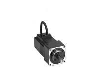
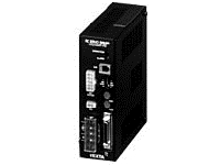
Geared Motor/Control Circuit
This product is currently no longer available for sale.
| Product Classification | Product Name | List Price | Shipping Date |
|---|---|---|---|
| Geared Motor / Control Circuit | AIP275CM-P5 | - | Discontinued Product (1.4.2013 discontinued) |
Included
- Actuator, Control Circuit, Parallel Key, Control I/O Connector, Varistor, Operating Manual
Specifications
Other Specifications
Driver Circuit Specifications
| Control Method | Sinusoidal PWM method |
|---|---|
| Speed and Positioning Control Command | Pulse Input |
| Maximum Input Pulse Frequency | 1000 Pulse/Setting: 50 kHz |
| 500 Pulse/Setting: 25 kHz | |
| Protective Function | When the following protective functions are activated, an alarm signal will output, and the motor will come to a coasting stop. Overheat protection, overload protection, overvoltage protection, speed error protection, motor disconnection protection |
| Input Signals | Photocoupler Input Input resistance: 220 Ω Input current 7~20 mA (clockwise pulse, reverse pulse, hold-off, counter clear) |
| Output Signals | Photocoupler and open-collector output, external use conditions 5~30 VDC max., 15 mA max. (positioning completion, alarm, timing, feedback pulses phase A and B) Line driver output equivalent to 26C31 (feedback pulse phase A and B) |
General Specifications
Values are after rated operation at normal ambient temperature and humidity.
| Classification | Motor | Driver | |
|---|---|---|---|
| Insulation Class | Class B (130 °C) [UL/CSA is approved to Class A (105 °C)]. |
- | |
| Insulation Resistance | Value measured between the case and coil using a 500 VDC megger is 100 MΩ min. |
100 MΩ or more when a 500 VDC megger is applied between the following places.
|
|
| Dielectric Strength | No abnormality was observed even when 1.5 kV at 50 Hz is applied between the case and coil for 1 minute. |
Sufficient to withstand the following for 1 minute.
|
|
| Operating Environment (When operating) |
Ambient Temperature |
0~+50 °C (Non-freezing):
PL geared type , standard type
0~+40 °C (Non-freezing):
Harmonic Geared Type
|
0∼+50 °C (Non-freezing) |
| Ambient Humidity | 85 % max. (Non-condensing) | ||
| Atmosphere | No corrosive gases or dust. No exposure to water, oil or other liquids. | ||
| Shaft Runout | 0.05 T.I.R. (mm)* | - | |
| Concentricity of Installation Pilot to the Shaft |
0.075 T.I.R. (mm)* | - | |
| Perpendicularity of mounting surface to shaft |
0.075 T.I.R. (mm)* | - | |
- *T.I.R. (Total Indicator Reading): The total dial gauge reading when the measurement section is rotated once around the reference axis center.
Note
- Do not measure insulation resistance or perform a dielectric strength test while the motor and driver are connected.
Permissible Radial Load and Permissible Axial Load
| Product Name | Permissible Radial Load | Permissible Axial Load | |
|---|---|---|---|
| Distance from Shaft End | |||
| 10 mm | 20 mm | ||
| AIP030-□■ | 57 | 75 | Use half of self-weight of motor as a reference. |
| AIP275-□■ | 112 | 134 | |
| AIP4150-□■ | 165 | 192 | |
| AIP275□■-P5 | 150 | 190 | 50 |
| AIP275□■-P7.2 | 200 | 250 | |
| AIP275□■-P10 | 250 | 320 | |
| AIP275□■-P25 | 300 | 380 | |
| AIP275□■-P36 | 350 | 450 | |
| AIP275□■-P50 | 400 | 510 | |
| AIP5150□■-P5 | 450 | 590 | 200 |
| AIP5150□■-P7.2 | 550 | 720 | |
| AIP5150□■-P10 | 600 | 790 | |
| AIP5150□■-P25 | 850 | 1120 | |
| AIP5150□■-P36 | 950 | 1250 | |
| AIP5150□■-P50 | 1050 | 1380 | |
| AIP030□■-H50 | 230 | 350 | 200 |
| AIP030□■-H100 | |||
| AIP275□■-H50 | 370 | 480 | 400 |
| AIP275□■-H100 | |||
| AIP5150□■-H50 | 1230 | 1410 | 1300 |
| AIP5150□■-H100 | |||
- Either A or C indicating the power supply input is specified where the box □ is located in the product name.
A2, A, B2, B, or M indicating the shape is specified where the box ■ is located in the product name.
Cables and Accessories
close