Induction Motors KII Series
4IK25SW-GHR15
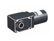
Geared Motor
This product is currently no longer available for sale.
| Product Classification | Product Name | List Price | Shipping Date |
|---|---|---|---|
| Geared Motor | 4IK25SW-GHR15 | - | Discontinued Product (31.3.2022 discontinued) |
Included
- Motor, Mounting Screws, Parallel Key, Safety Cover Set, Operating Manual
Specifications
Data Download
Other Specifications
General Specifications
| Item | Specifications |
|---|---|
| Insulation Resistance | 100 MΩ or more when a 500 VDC megger is applied between the windings and the case after continuous operation under normal ambient temperature and humidity. |
| Dielectric Strength | No abnormality is observed when 1.5 kVAC at 50 Hz or 60 Hz applied between the coils and case for 1 minute after continuous operation under normal ambient temperature and humidity. |
| Temperature Rise | After no-load continuous operation at normal ambient temperature and humidity, the winding temperature rise measured by the resistance change method is 80 °C max. (70 °C max. after rated load continuous operation for the three-phase type). |
| Thermal Class | 130 (B) |
| Overheat Protective Device | Built-in thermal protector (automatic return type) Open: 130 ±5 °C, Return: 85 ±20 °C |
| Operating Ambient Temperature | 0~+50 °C (Non-freezing) Three-Phase 220/230 VAC: 0~+40 °C (non-freezing) |
| Operating Ambient Humidity | 85 % max. (Non-condensing) |
| Degree of Protection |
Terminal Box Type:
IP66* (25 W, 40 W)
IP54 (90 W) Lead Wire Type:
IP20
|
- *For Materials and Surface Treatments
With Terminal Box Type: IP66
| Type | Output | Materials | Surface Treatment |
|---|---|---|---|
| Right-Angle Geared | 25 W, 40 W | Motor case and Terminal box: aluminum Output shaft: S45C Screws: Stainless steel (externally facing screws only) |
Motor Case, Terminal box: Painted (excluding installation surface) |
Permissible Radial Load and Permissible Axial Load of Gearhead
| Gear Ratio | 15 | 20 | 25 | 30 | 40 | 50 | 60 | 75 | 100 | 120 | 150 | 200 | 240 | ||
|---|---|---|---|---|---|---|---|---|---|---|---|---|---|---|---|
| Permissible Radial Load [N] |
Hollow Shaft | 10 mm From Mounting Surface | 850 | 1200 | |||||||||||
| 20 mm From Mounting Surface | 700 | 1000 | |||||||||||||
| Solid Shaft | 10 mm From the End of the Output Shaft | 700 | 1000 | ||||||||||||
| 20 mm From the End of the Output Shaft | 800 | 1100 | |||||||||||||
| Permissible Axial Load [N] | 300 | ||||||||||||||
System Configuration
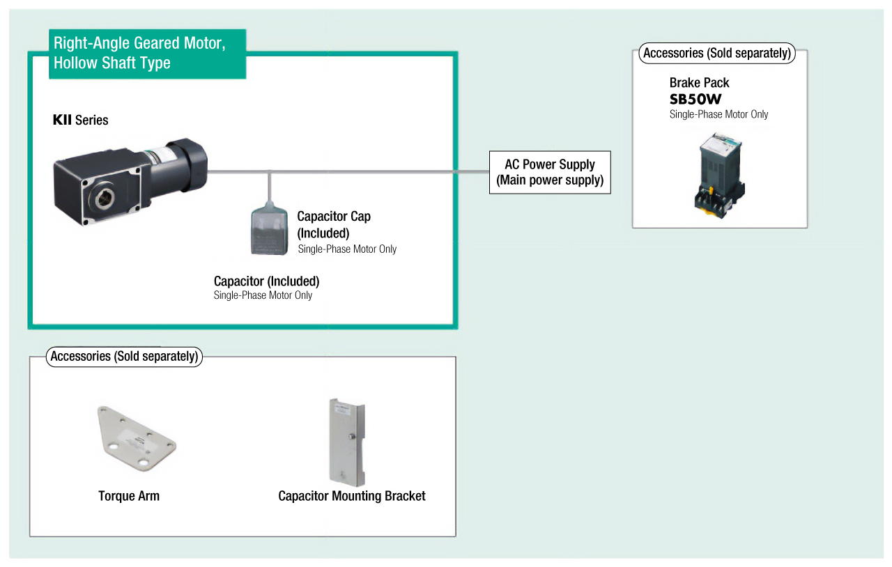
Cables and Accessories
close